MP110 and MP211 PLC Series Quick Installation Guide
Introduction
About The Mikrodiagram
Mikrodiagram; It is an editor software developed by Mikrodev and used for programming Mikrodev PLC family devices. With Mikrodev PLC programming editor Mikrodiagram, very complex projects can be realized quickly thanks to its visual and easy-to-understand interface.
In addition to basic logic blocks such as "AND, OR, XOR" in the Mikrodiagram library, there are also advanced blocks that will facilitate complex applications such as "PID, astronomical timer".
By connecting to devices via different interfaces (USB/TCP), tools such as program upload/update, online monitoring and firmware update are also offered with Mikrodiagram.
Mikrodiagram Setup
Mikrodiagram software is prepared to run on current Windows versions. The installation file can be downloaded free of charge from the following internet address:
http://www.mikrodev.com/downloads/mikrodiagram/MikrodiagramSetupSTM_latest.zip
Mikrodiagram setup is completed by following the instructions on the screen.
Creating A Project
The following steps are followed to create a new project in Mikrodiagram.
Creating A New Project
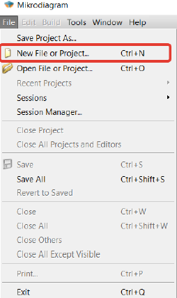
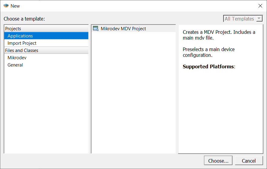
To create a new project in Mikrodiagram, choose "new file or project" from the "File Menu".
Step 1
Step 2
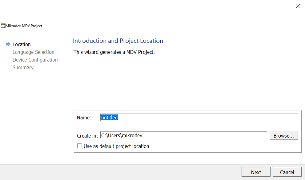
The newly created project name and project creation location are selected.
When "Use as default project location" is selected, the project creation location is fixed for projects that will be created later.
Step 3
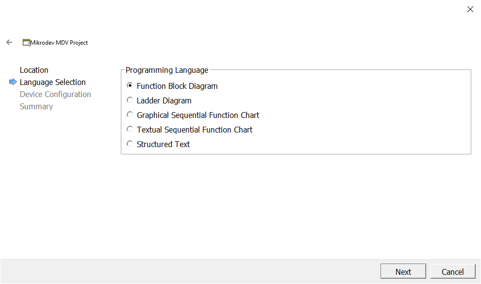
The programming method is selected.
Step 4
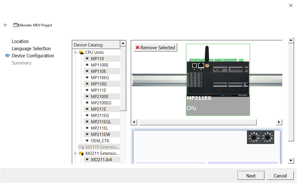
The device to be programmed and the expansion unit (if it needs to be added) are selected.
Step 5
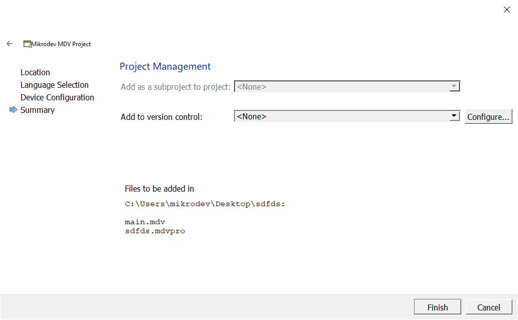
Project configuration settings can be changed.
Step 6
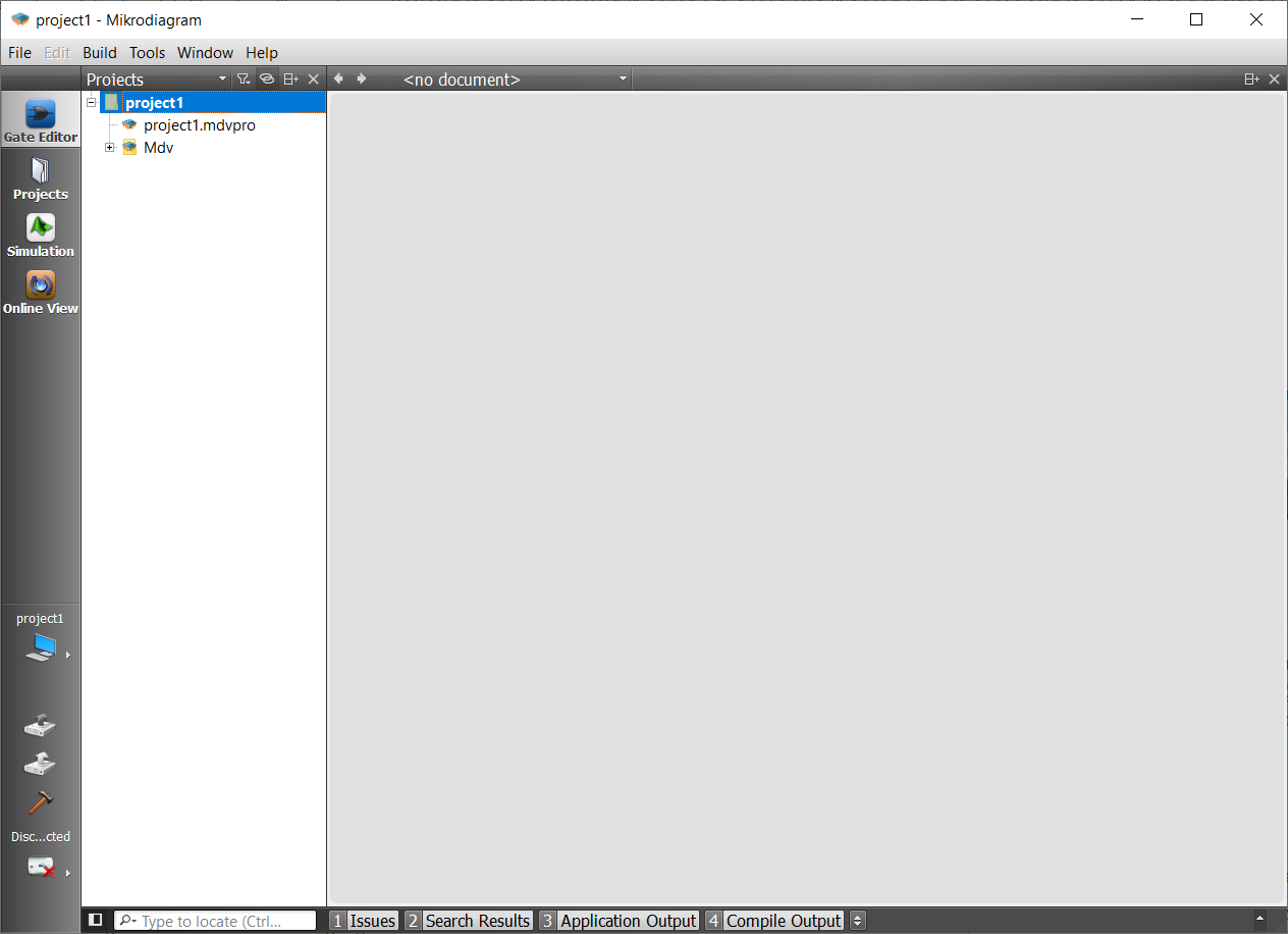
A new project has been created.
In the projects section on the left side tab, double-click the Mdv text or click the plus icon next to the Mdv text. In the bottom tab that opens, there is the file "main.mdv". Double-clicking on this file opens the page and the project design can be started on this page.
Connecting To The Device

The projects prepared in the Mikrodiagram must be sent to the device and a connection must be established to the device for online monitoring.
The device can be connected to the device via USB or TCP port in Mikrodiagram.
In Mikrodiagram, connection cannot be established from USB and TCP port at the same time.
Setting A USB Connection
In order for the USB connection to be established, the USB driver installation must be completed on the computer with the Mikrodiagram installed.
There is no need for USB driver installation on computers with Windows 10 and above operating systems.
After the USB Driver installation is completed, a USB cable connection is made between the computer and the device.
"USB A and USB B" (printer cable) should be preferred for USB cable selection. The USB B side is connected to the device and the USB A side is connected to the computer.
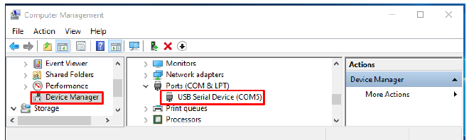
The COM port where the USB cable connected from the device manager is defined is determined.
The connection
interface is accessed by clicking the tab from the Build Mod options.
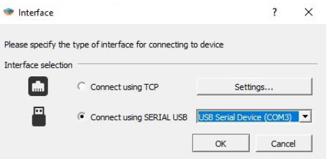
"Connect using SERIAL USB" is selected, COM port is selected. With the "OK" button, the connection establishment process is started.
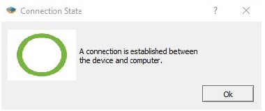
When the message "USB connection has been established between the device and the computer via serial port" is received and the connection button is turned to the "connected"
 position, the connection via USB is completed.
Setting A TCP Connection
In order to establish a TCP connection between the computer and the device;
At least one of the "ethernet, Wi-Fi or GSM" ports must be present on the device to which a TCP connection will be established.
Establishing A TCP Connection with Ethernet
In order to establish an Ethernet connection;
The device must have an ethernet port.
Ethernet cable (CAT5, CAT6) connection must be established between the device and the computer.
If the device and the computer are in the same local network, the defined IPs should be selected accordingly.
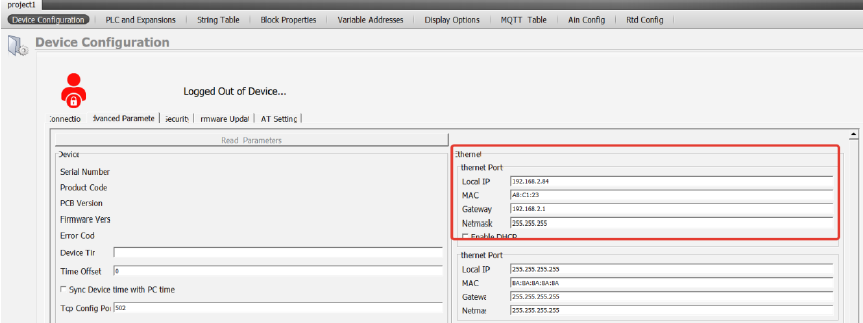
Identifying IP To The Device
"Mikroterminal" program should be used to make device IP settings via USB connection. (See "Using the Mikroterminal" section.)
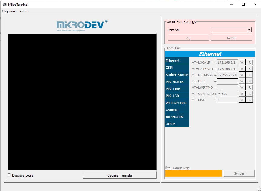
The Mikroterminal program can be accessed from the Mikrodiagram "Tools" menu.
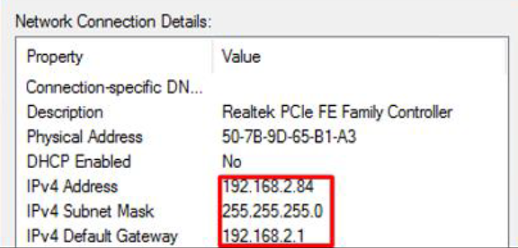
After the device and computer IP settings are complete, "ping" must be done from the computer to the device for the "ethernet cable connection test" between the device and the computer.
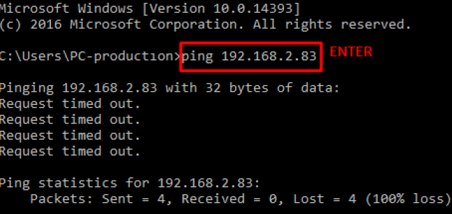
For the "ping" operation, the device IP is typed into the computer "command window" as in the picture and "ENTER" is clicked.
If the result output in the upper picture occurs, it means that the ping operation "failed". IP settings and ethernet cable connections should be checked again.
If the result is output as in the picture below, the pinging process is "successful".
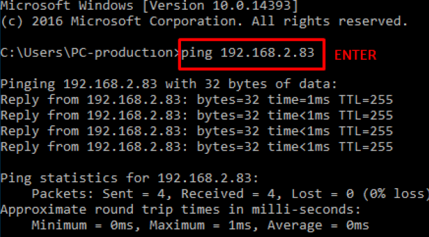
It means that an ethernet TCP connection can be established from the Mikrodiagram to the device.
Defining A Listening Port To The Device
In Mikrodev products, the standard listening port is defined as 502.
To change the listening port, which is the standard 502;
TCP socket block should be added to the project prepared in Mikrodiagram.
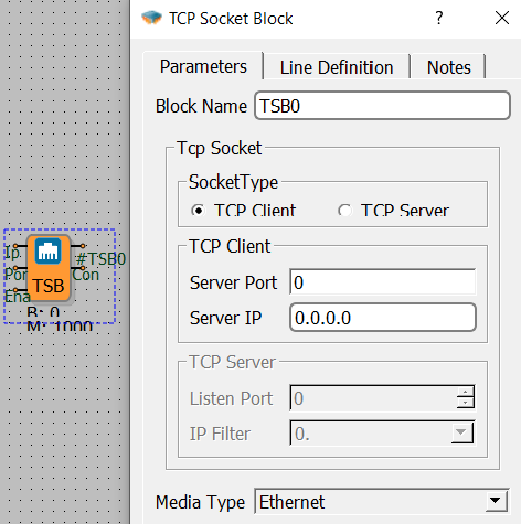
Socket type "TCP server" is selected.
The listening port is defined.
As the "Media type", one of the Ethernet, GSM or Wi-Fi options is selected.
Note: In the Mikrodiagram project, listening ports can be defined as many as the number of TCP socket blocks added as a server.
Ethernet Connection Test
After making the necessary settings for the Ethernet connection, for the TCP connection;
Click the link tab in the Build mod options.
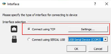
Click "Settings" in the window that opens.
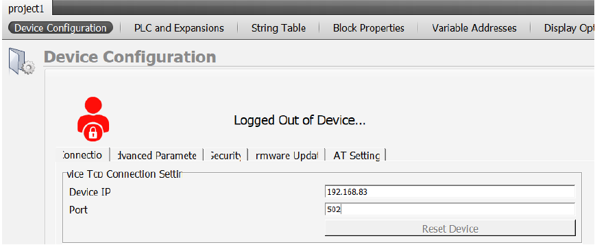
In the window that opens, the device IP is written in the "Device IP" section and the device listening port is written in the "port" section.
Select "Connect using TCP" and click "OK" to wait for the TCP connection to be established.
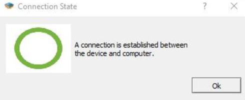
When TCP connection is established, "TCP connection established between device and computer" warning is displayed on the screen.
 The connection icon is also displayed as "Connected".
Establishing TCP Connection with GSM
In order to establish a GSM and TCP connection to the device in Mikrodiagram;
The device must be GSM-enabled.
The GSM antenna of the device must be installed.
Device signal quality (CSQ) should be between 1-31.
A SIM card with data package (internet package) must be inserted into the device. (SIM card must have fixed IP.)
APN definition of the inserted SIM card must be made to the device.
The computer with the Mikrodiagram must be connected to the "wide area network" (WAN) (internet network).
Identifying IP To The Device
In order to establish a TCP connection from the Mikrodiagram to the GSM-enabled device, the GSM IP is written in the "device IP" section.

Other than GSM IP identification, other operations are the same as Ethernet TCP connection.
Loading A Mikrodiagram Project To The Device
There are 2 methods to load the project prepared in Mikrodiagram to the device.
The project can be sent to the device via USB or TCP connection.
Upload Project Via USB Connection
After the USB connection is established between the device and the computer,
 the "send to device" button is clicked. The project file is compiled and the bin file is loaded on the device.
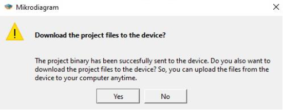
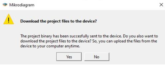
The confirmation screen opens for the project file backup to be uploaded to the device. If "Yes" is clicked, then the project file will be extracted from the device.
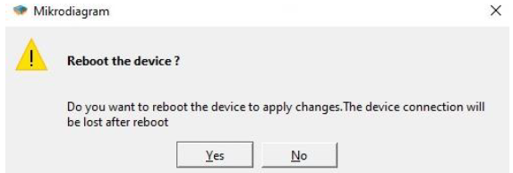
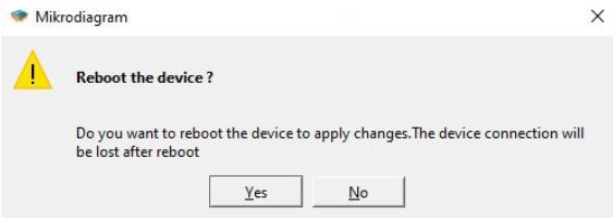
The device must be restarted in order for the changes to be applied. A confirmation screen appears for device restart. Click on "Yes".
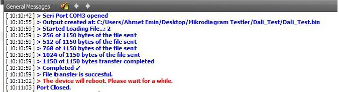
If the following output occurs in the "incoming messages" section of the Mikrodiagram, it means that the Mikrodiagram project has been successfully loaded to the device.
It should be noted that the file upload process is 100% complete. The device restarts automatically when the project upload process is 100% completed with the USB connection. (it is reset.)
Upload Project With TCP Connection
After the USB connection is established between the device and the computer,
the "send to device" button is clicked. The project file is compiled and the bin file is loaded on the device.
The confirmation screen opens for the project file backup to be uploaded to the device. If "Yes" is clicked, then the project file will be extracted from the device.
The device must be restarted in order for the changes to be applied. A confirmation screen appears for device restart. Click on "Yes".
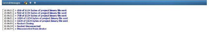
If the following output occurs in the "incoming messages" section of the Mikrodiagram, it means that the Mikrodiagram project has been successfully loaded to the device.
It should be noted that the file upload process is 100% complete. The device restarts automatically when the project upload process is 100% completed with the TCP connection. (it is reset.)
Drawing A Project File From The Device
The existing project in the device can be downloaded to the computer via the Mikrodiagram program. For this, the following steps should be followed.
When the device is powered and connected to the computer via TCP or USB;
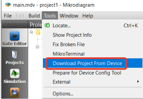
Click on the "dowload project from device" option in the tools section of the Mikrodiagram.
When the download status monitoring is at 99%, the file location where the project is to be saved is selected.
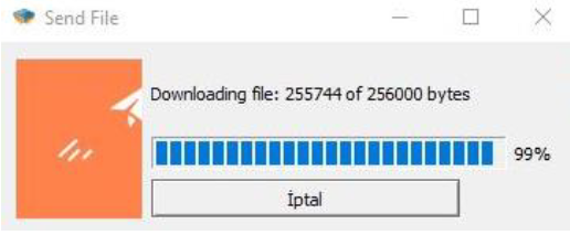
From here, the location where the file should be saved is selected. Thus, the bin file in the device is downloaded to the computer.