ViewPLUS SCADA Editor
Introduction
What is SCADA?
SCADA is an abbreviation created by reading the first letters of the words "Supervisory Control and Data Acquisition." SCADA, a comprehensive and integrated database control and monitoring system, provides automatic control, monitoring and reporting of all electronic units of a facility or operation. SCADA systems are expected to perform the functions of monitoring, controlling, collecting data, recording and storing data. The SCADA systems can operate in continuous, intermittent, repetitive or discrete modes in industrial processes, manufacturing, production, power generation, wastewater treatment, oil and gas pipelines, electricity transmission and distribution, wind generators, civil defense siren systems and major communication systems , water treatment and promotion centers in the sectors. May include public and private facilities, including space stations. Access to heating and ventilation systems (HVAC) and control and monitoring of energy consumption may be required. SCADA's maximum benefit will continue to be from the greatest needs of industrial installations in terms of safety and convenience.
Mikrodev ViewPLUS SCADA
ViewPLUS is a SCADA software developped by Mikrodev. While ViewPLUS is being developed, stability, ease of use and visuality are kept in the foreground. With ViewPLUS, it is possible to provide visual monitoring, control and evaluation of any kind of automation unit and system.
We can summarize some features that ViewPLUS has:
Large Visual Library
Allows users to easily prepare their own SCADA components as well as the large visual library.
Redundant Working Mode
Field data is read and processed by BACKUP server in case of the failure of the primary server. No data loss Communication status tests (field devices or spare SCADA)
Server / Client Architecture
Multi-station support Assigning authority level to work stations
Licensed Tag Capacity
Unlimited license (limited to system memory). Ability to define alarm tags up to the number of tags Ability to identify trends by the number of tags
Operating System Support
Windows 7/8/10 Windows Server 2008/2012/2016 Linux (Debian) MacOSX
Security
128 different access authorization levels for tags and pages Ability to assign 128 different group memberships to users Integrated security with operating system TLS / SSL versions of layer 7 protocols on comms Use explicit SHA256 summaries instead of plain text passwords in the authorization mechanism
Data Transfer
SQL compatible data transfer possibility inside and outside
Alarm
Ability to define alarms for all defined tags Alarms can be defined 256 different criticality levels Ability to monitor active alarms and alarm history Alarm monitoring by date and importance Output from alarm list: Excel, printer, pdf
Data Record Trend Monitoring
Log recording capability for all defined tags Trend defined tags graphical display Export of trend defined tags data to excel, pdf or printer
Communication
Excellent connection with MikroDev PLC, REMOTE IO and Gateway products Compatible with a wide range of industry standard protocols: MODBUS TCP, MODBUS RTU, DNP3, SNMP, IEC- *, BACNET
Database Support
PgSQL (PostgreSQL 13)
ORACLE
SQLite
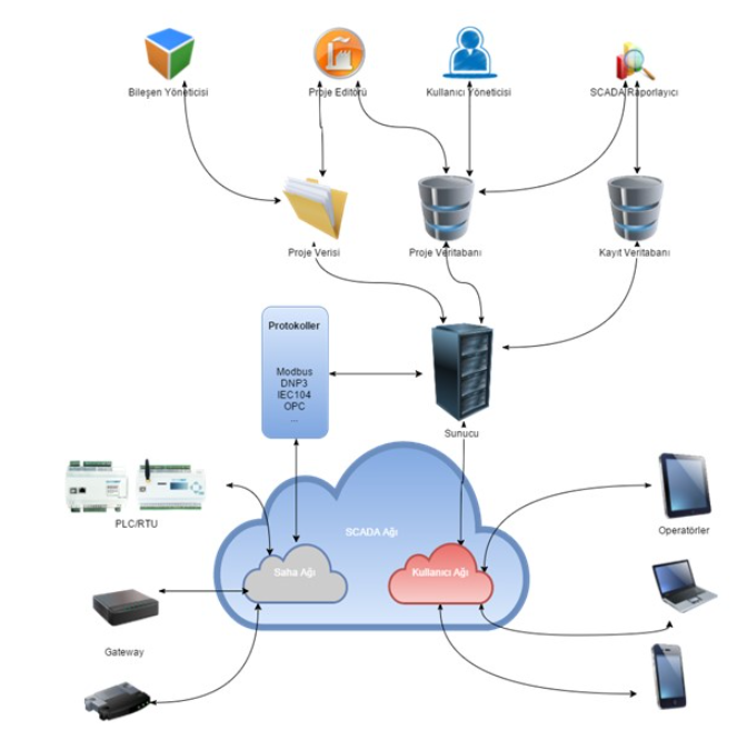
Architecture
Mikrodev SCADA server provides real-time monitoring and control of field devices by connecting to this devices via intranet or internet. It saves collected data in the tag, event and alarm database. It also allows users connecting to the server over the internet to monitor and control the devices on the field using the prepared SCADA project. While different combinations can be created according to the network and hardware topology designed with ViewPLUS, the architecture shown below can be used basically.
Creating New Project
To create a new project:
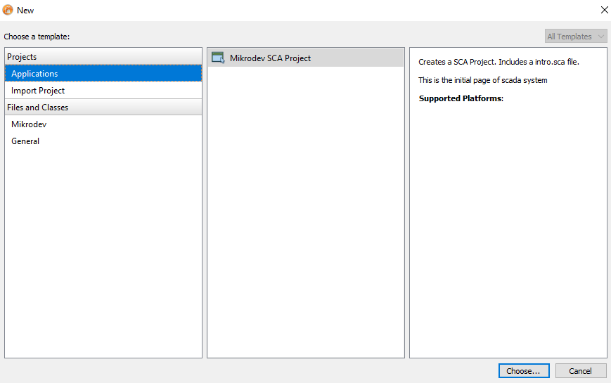
Select File>New File or Project > Mikrodev SCA Project
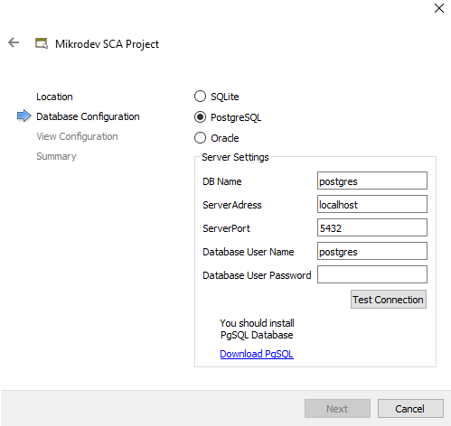
Select project name and location.

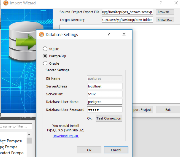
After entering the database username and password, you can verify the password by clicking the "Test Connection" button (if you will use PostgreSQL database and the PostgreSQL database is not installed on your system, you need to download and install the relevant version by clicking on "Download PgSQL" link.)
The visual parameters such as screen color, default page size are set.

If you are going to use the SVN version control tool on the next page, the settings will be adjusted accordingly.
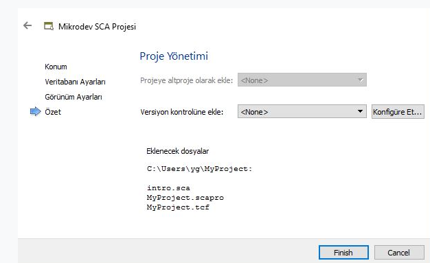
A new project is created by pressing the "Finish" button. The newly created project consists of 2 files. These are the files with the extension "scapro" where the project configuration parameters are stored. You do not need to make any changes to this file. The other file that is automatically created is the file named "intro.sca". You can design the main screen on this page.
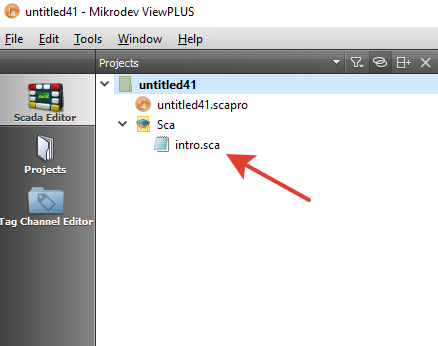
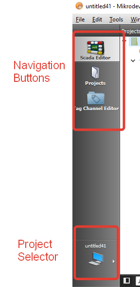
On the far left is navigation buttons that allow you to navigate through the editor's basic interfaces. Using these buttons, you can switch between the SCADA Editor view, Projects view and the Tag/channel Editor view. At the bottom of the navigation buttons is the project selector. If more than one project is open at the same time on the editor, this button can be used to switch between projects.
For detailed information: Creating the project.
SCADA Editor View
Sidebar
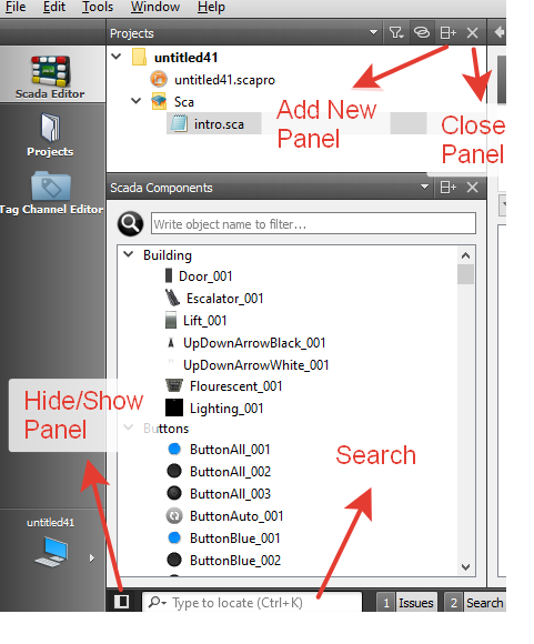
The sidebar is available in the SCADA Editor view. Use the sidebar to browse projects, files and insert components.
Project files and components are controlled using panes on the left side of the editor. You can also filter and search the project files via the search box at the bottom of this panel. At the bottom left of the panel is a button that allows you to hide and show panels.
You can select the content of the sidebar in the sidebar menu:
Projects shows a list of projects open in the current session. Open Documents shows currently open files. File System shows all files in the currently selected directory. You can change the view of the sidebar in the following ways:
To toggle the sidebar, click  (Hide Sidebar/Show Sidebar) or press Alt+0 (Cmd+0 on macOS). To split the sidebar, click  (Split). Select new content to view in the split view. To close a sidebar view, click  (Close).
Components
ViewPLUS SCADA offers components in different types for visualization of the displayed data. These are; basic components, timers, graphics, database query and text components.
The basic components are located in the "SCADA Components" pane in the left panel of the Editor. The other components can be created using the "components toolbar" on top of the editor window.

Basic Components
Using the "Component Manager", different objects that the user has defined can be added . To insert a component to the current page, press the left mouse button on one of the components in the panel, then press the desired position on the scene with the left mouse button again and the component is added.
To change the size of the added component, you can move the triangle icon in the lower right corner of the component with the mouse. "Object Properties Panel" is used to change the advanced properties of the component.
Text Component
The text component is used to display text in different fonts, colors, and formats. Used for fixed text. You can change the formatting of the text in the "Format" tab in the toolbar.

You can show dynamic content on text component.
You can add dynamic content on some components. To achieve this, you should use the '$' operator and 'braces' ($ {....}):
${Tag_ID}
As an example, you should write '${1234}' onto your component to display the value of a tag with the tag ID '1234' in your system.
Tank Level is ${1234}
this expression will be shown on the component like:
Tank level is 78
While working with "double precision" numbers, you can use "printf text format"(see section Object Properties Panel) to change the precision of the displayed value:
Tank Level is ${1234,%.3f}
If the value of the tag with ID '1234' is a double precision number like "567.123456", this expression will be displayed on the component like:
Tank level is 567.123
Timer Component
You can control the "Timer Blocks" that you have added to the PLC project with Mikrodiagram software via the "Timer" component. By adding "Timer Tags" you have defined in the Tag/ Channel Editor to the timer component, users can change the timing settings through the client software.
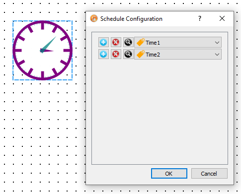
Chart Component
Using the chart component, you can graphically view the data of the desired tags. Chart object displays graphs as lines or bar graphs. In the chart settings window, the chart's appearance, behavior, and parameters for the tags to be displayed can be set.
While only the last values of the tags added are shown on the bar chart; historical values of tags can be displayed on the line chart.
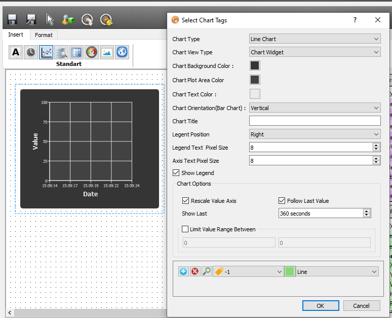
Chart View Type: Sets how the chart will work. Chart Component : Graphical representation of the added component.
Link to Chart : The added component only acts as a button. A separate window chart display is shown when pressed.
Chart Type: Selective type for chart type Line Grid : The trend data of the defined labels are drawn with different colors on the same chart . With new data read from the field, the chart is updated once in a second. Bar Chart: Defined tags are displayed in bar chart format. The chart is updated once in seconds.
Database Query Component
This component allows the client to retrieve some specific queries from the database. In the Database query settings window, parameters related to the tag to be queried, query type, range, update frequency, and component visibility can be set.
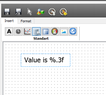
Table Component
You can display the data in tabular form on the table component. You can add and remove new columns / rows to table via the table menu .
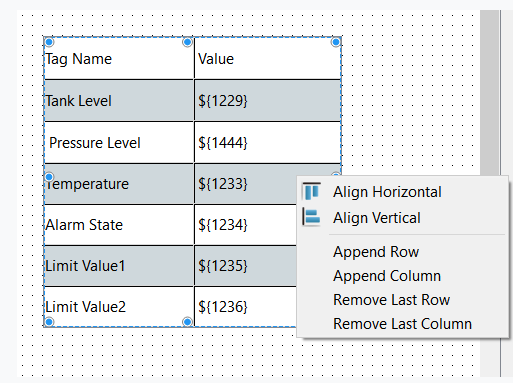
Styling Table
You can set font and color for cell text using the format toolbar on the top of the editor:

You can also change the appearance of the table itself using stylesheets. Here is a sample stylesheet for changing row colors:
alternate-background-color:#AACA98;
background-color: #D3E3D0;
Formulas on Table
You can use excell like formulation on table cells.
Supported functions are:
SIN COS TAN COT ABS LOG LOG10 SQRT POWER ROW COLUMN PI SUM PRODUCT MIN MAX AVERAGE MEDIAN MODE
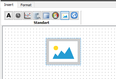
Image Component
You can add images into your view by using image component. You can resize, rotate and flip the added image.
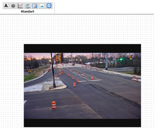
Web Frame Component
You can add web content into your view by using Web Frame component. You can resize, rotate and flip the added frame. This component is useful, for example when you need to add a web camera view into your SCADA page.
Web frame view is not supported on mobile versions of OperatorClient.
Add Objects Mode
Object Insertion Mode is used to bring the last used scada component to the editor screen.
Page Properties Panel
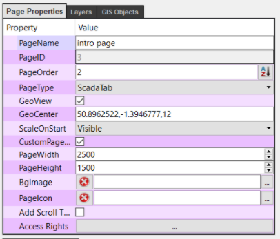
The basic settings for the page are set via this panel
Page Name
The name you want to appear for the page in the left panel on the client screen for pages set as tabs.
PageID
System-assigned unique ID for each page.
PageOrder
Sets the order in which the page will appear in the left panel on the client screen for pages set as tabs.
PageType
There are three different page types. "Tab" type pages appear as full screen on the client. At the same time, a button is created in the left-hand navigation panel that provides access to this page. Unlike the "Tab" for the "Linked Page" type, there is no button on the navigation panel. "Dialog" type pages are pages that are configured as popups to be opened in an action repository.
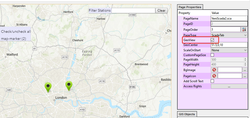
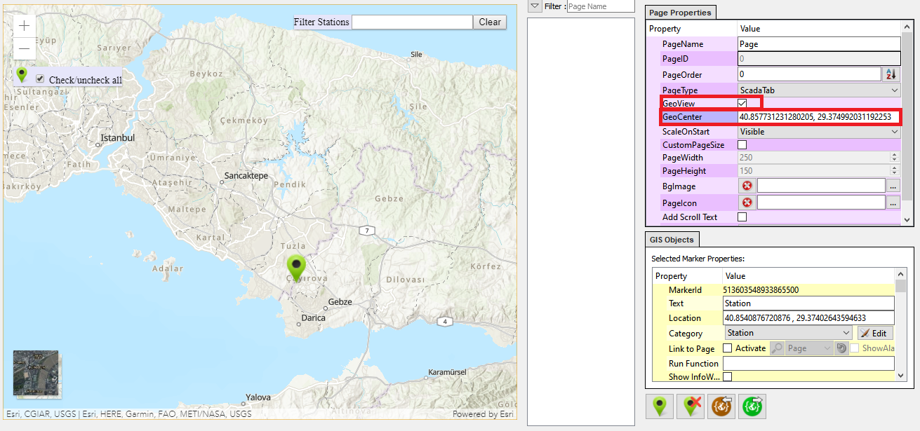
GeoView
Enables Google Maps api and shows the map. You should provide a map API key to be able to use this feature. First login to Google, go to Google API Key Console and select "Google Maps JavaScript API". After you get the key insert this into "Projects > Project File Paths > Map API Key"
GeoCenter
This option determines the initial position and zoom level of map when opened. It should be in that format :" Longitude,Latitude,ZoomLevel" Scale at startup Set how to scale scaling when the page is first opened on the client screen.
CustomSize
This option is checked if a different size will be used in the project settings instead of the default page size.
Page Width
Width for custom page size
Page Height
Height for custom page size
BackgroundImage
An image to be displayed on the client screen for the page in the left panel is displayed for the pages set as tabs.
Add Scroll Text
Adds a slip at the bottom of the page that allows you to show informative messages.
AccessRights
Different access rights can be defined to restrict access to the page. For users who do not have these rights, the page is not displayed.
Layers Panel
You can create or delete a new layer on the Layers panel. You can create a hierarchical layout on the page by creating components on the layers you create. You can make complex designs easier by hiding / showing layers. Another benefit provided by the layers is that the visibility of the layers at different zoom levels can be changed.
Hide / Show Layers
You can hide / show the layers you have added using the "Hide / Show Layer" option on the right-click menu of the mouse.
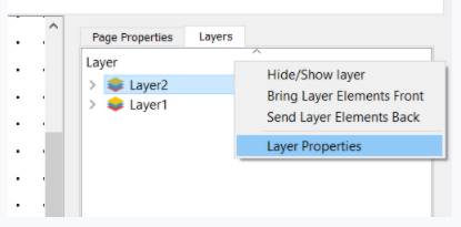
Changing the Order of the Components in the Layer
You can change the order of the layers that you have added using the "Bring Layer Components Front" or "Send Layer Components Back" options on the right mouse button menu.
Hide / Show Layers According to Scale Level
You can hide and show the layers defined on the page according to the scale level of the screen. On this scale, you can display more detailed information components when the scale level increases, but you can reduce the complexity of the design and make it easier to use by showing fewer components when the scale level increases. To do this, first select "Layer Properties" in the "Layers Panel"
In the dialog that appears, there are two fields showing scale level parameters.
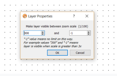
The layer will be visible between the two scale values to be entered here. If you define one of the values as "-1", the layer will be continuously visible in this direction regardless of the scale. For example, if values of "300" and "-1" are considered, the result will be like that: "Make the layer visible if the scale is greater than 3"
The scale is smaller than '3':
The scale is higher than '3':
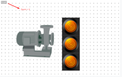
As you can see in the picture, when the scale value goes up to '3', the layer with the buttons becomes visible.
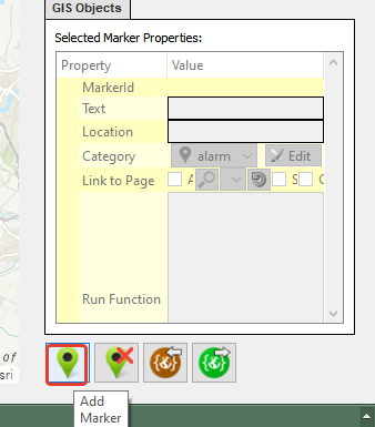
GIS Objects Panel
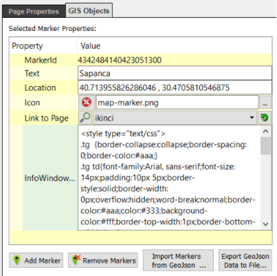
You can edit your maps using this panel.
Text
The marker's name that will show up on map.
Location
The marker's location on map. It should be in "Longitude,Latitude" format
Icon
Custom marker icon to be used on map
Link to Page
Select a page link to go when the marker is clicked. You can enable or disable page linking. When you disable page linking "Go To Page" button will disappear on infowindow. You can also enable/disable of showing alarms of the target page on the marker from this panel.
Info Window
Here you can insert any html content to be shown on Info Window for each marker. You can use ${tag_id} and #{operation} syntax inside html elements.
Add Marker Button
Click on the map after selecting this button to insert a new marker
Remove Markers Button
Click on the map after selecting this button to remove markers
Import Markers from GeoJson Button
You can import markers from a geoJson file using this button. Go to https://geojson.io for more information.
Object Properties Panel
It is a panel that allows you to adjust the SCADA objects added to the page.
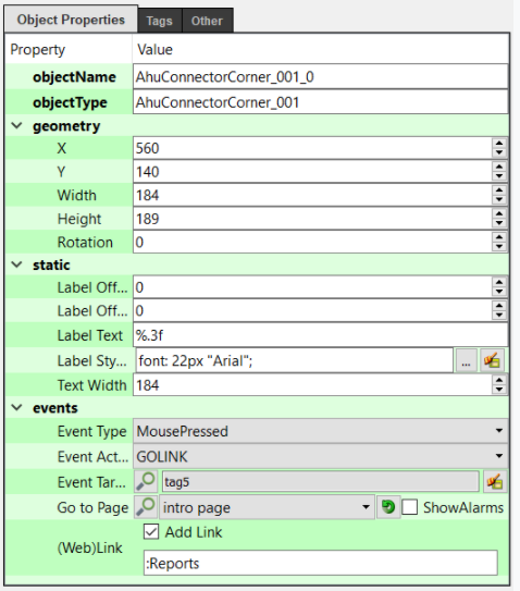
Object Name
A name that makes it easy to distinguish the object.
ObjectType
Represents the component type of the object.
Geometry
The position of the object on the screen is the parameters related to the scale and rotation. The top leftmost point of the page is positioned by accepting the point (0,0). Position value increases down and to the right.
Constants
Contains some settings related to the appearance of the object.
Font X Offset : Used to add a horizontal offset to the position of the text to be printed on the object, relative to the upper left corner of the object.
Font Offset : Used to add a vertical offset to the position of the text to be printed on the object, relative to the upper left corner of the object.
Text Content : It is the field in which the display format of the "Text Label" defined in "Feature Tags" is configured. The "formatted" text entered here is printed on the component. The text to be entered must be in "printf text format". The following examples can be used for formatting:

Integer             :% d    => "1977"
Add leading spaces  :% 10d  => "1977"
Add a leading zero  :% 010d => "0000001977"
Float numbers       :% 4.2f => "3.14"

You can also display date/time values read from a 'seconds' source in desired format. To achieve this you can use "%dt(...)" notation. "%dt(...)" notation assumes that the tag value is in seconds:

Date is : %dt(dd.MM.yyyy / hh:mm)  will be displayed as:

Date is : 13.05.2017 / 12:24
Font Style Sheet : By setting the style sheet for the "Font Content" to be displayed.
Text Width : The maximum width of the text to be displayed on the component.
Events: Contains user interaction settings.
Event Type : The parameter that determines when the event will be fired.
MousePressed: Left mouse button press event
MouseReleased: Left mouse button release event   Keystroke: Keyboard push event

Event Action : When "Event Type" is triggered, the function to be operated is selected.
SET           : Sets the value of "Target Event Tag" to "1".   CLEAR: Makes the value of "Target Event Tag" "0".
CHANGE        : Makes "0" if "Target Event Tag" is "1" and "1" if it is "0".
LOADVALUE     : If this function is selected, users will have a dialogue page in the client software where they can right-click on this component mouse to change the value of "Target Event Tag".
NEXTPAGE
PREVIOUSPAGE
GOPAGE        : The page that was selected in "Go to Page" opens on the screen.
GOLINK        : The link defined in "WebLink" is executed.

Target Event Tag : Defines the tag that is the target of the "Event Action"
Go to page : Page selection for "Go to page" action
(Web)link: If this field is defined as a web link, a menu entry will be created to access the related page from the right-click menu of the component. You can also create direct link to Alarms page by writing ":Alarms" expression or to Reports page by writing ":Reports" to this field or to previous page by writing ":Back". Other than that you can directly create a link to a report query in this field.
For detailed information: Component Event Type and Event Actions.
Tags Panel
The values read from the labels selected from this panel are constantly updated according to the values read from the field.
The labels defined here can also be used in macros. For each label, there are predefined "i, o, s, w" values. (Such as i1, i2, o1, o2 ..). You can see the default variable names of the tags by hovering over them with the mouse.
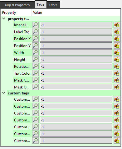
Feature Tags
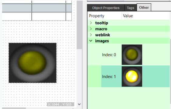
Image Index Tag: Shows the image index of the component to display instantly. Which images is in which index can be changed using the "Component Manager" or can be viewed under "Other Tab".
Text Tag: The value of the selected tag here is displayed on the component according to the form specified in "Text Content".
X Position: The horizontal position coordinate of the component is taken from this parameter. The top left corner of the page is the (0,0) coordinate. As you go to the right, the X value increases.
Y Position: The vertical position coordinate of the component's screen is taken from this parameter. The top left corner of the page is the (0,0) coordinate. The Y value increases as it goes down.
Width: The width value of the component is read from this label.
Height: The height value of the component is read from this label.
Rotation Angle: Rotation angle of the component with X axis. Gets value in degrees.
Text color: The color of the text to be displayed on the component is taken from this parameter.
Mask color: The color of the mask that will be applied on the component is taken from this parameter.
Hex value of "112233" of the RGB color value defined as # 112233 is taken as the integer counter value. You can find some sample hex color values here. And you can use this tool to convert the color valueto integer.
Mask transparency: A value from 0-255 is taken from this label for the transparency value of the masquerade to be displayed. Custom Labels: The 7 labels you select here will be available to the macros.
Other Settings Panel
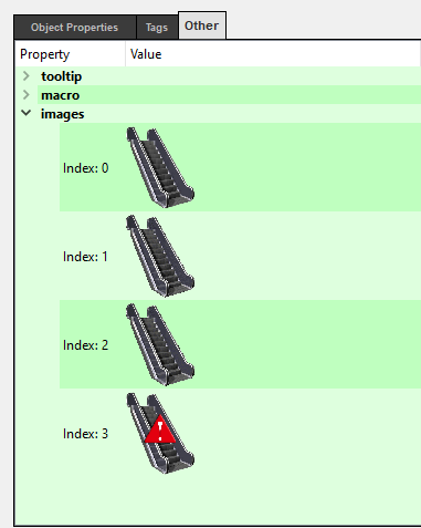
Limits: The maximum and minimum values by which users can change the "Target Event Tag" value through the client software are set using these parameters. ToolTip: Adjust the content that will be shown when users bring the mouse over the component in the client software. You can show dynamic content on tool-tips . Please refer to Basic Scripting. Macro: The script for the component is written in this box . For more information about macros, see the corresponding section. Images: The images and index numbers defined for the selected component are displayed in this area. Index number expresses which image to show according to the data value read from the tag value of "Image Index Tag" at "Tags Panel". You can change the index display order of components from this panel
You can move up or down image indexes from the context menu opened by right clicking on the images.
For detailed information: Limit, Hint, Macro and Index Assignments.
Projects View
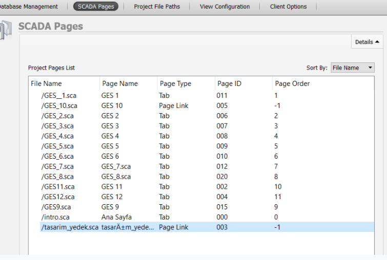
SCADA Pages
List of all pages created on the project. This view gives detailed information about the created pages for the project.
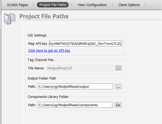
Project File Paths
Here are some important folder paths related to the SCADA project
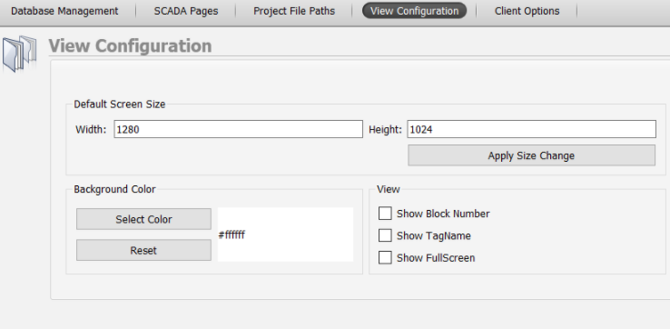
View Configuration
Default settings for SCADA pages are configured using this menu.
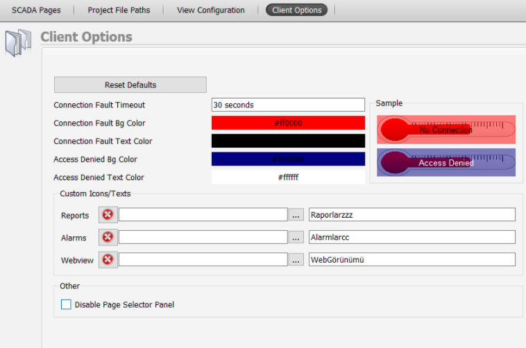
Client Options
Various settings related to Client view can be done on this menu.
Tag and Channel Editor View
Channels and tags are special definitions that enable the SCADA software to access the data on the field devices. Channels include protocol definitions to provide communication with the device on the field and specific settings for this protocol. Tags consist of address definitions for the registers on the connected device. Alarm management is also done under this view.
Channels
Channels containing connection definitions can be created with a device in the field, as well as special channels defined by virtual connections such as macros or database queries.
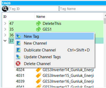
To create a new channel, open the "Tag Channel Editor" tab, press the right mouse button on any channel, and select "New Channel" from the popup menu.
In the dialog that is opened, necessary adjustments can be made about the new channel.
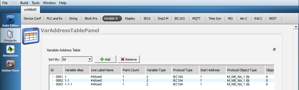
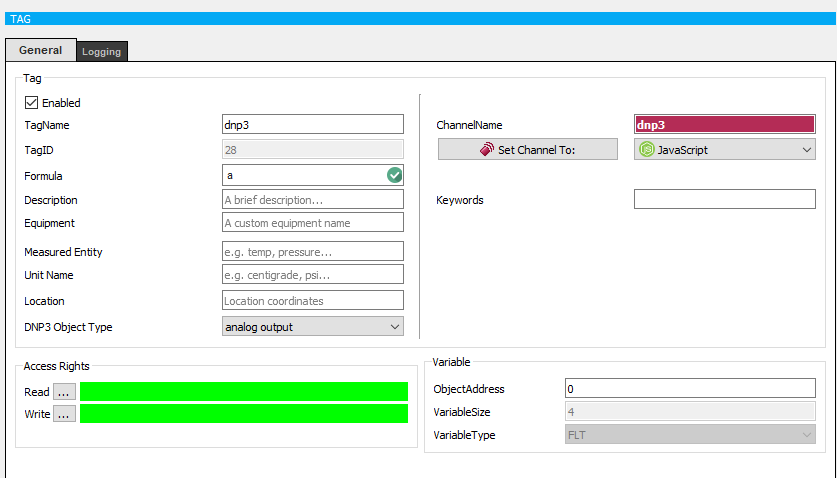
Tags
"Tag" refers to point data that is read from the scene or created virtually by the system. Tags are defined under the channels and may have different properties depending on the type of channel they are in.
Creating Tags
To create a tag, open "Tag/Channel Editor Panel". Tag/Channel pane is on the top left of the screen. On the pane, right click on the channel in which you want to create a tag. On the context menu select "New Tag" action.
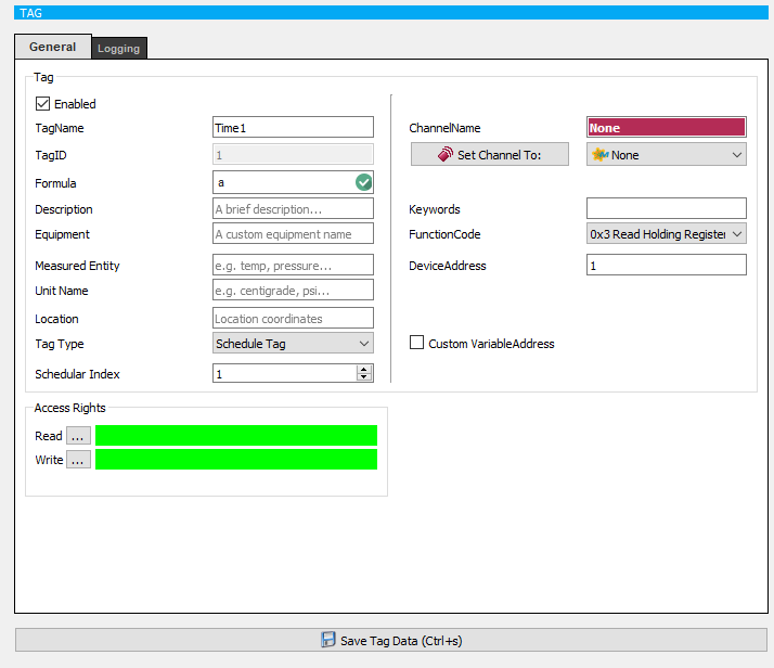
On the "New Tag" dialog write a name and description for the tag. The "tag name" must be unique; if you select an existing tag name, the system will prompt you a warning.
All tags created in the system have common properties that can be changed. These features are:
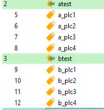
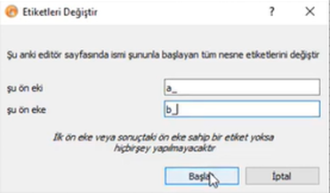
Multi-Label Exchange
The letters after the prefix of the labels on the components to be changed must be the same as the letters after the prefix of the labels to be put.
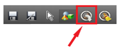
To change multiple labels, click the Change Labels tab.
When the necessary action is taken in the Change Labels window, the multi-label change process is completed.
For detailed information: Multi-Label Exchange.
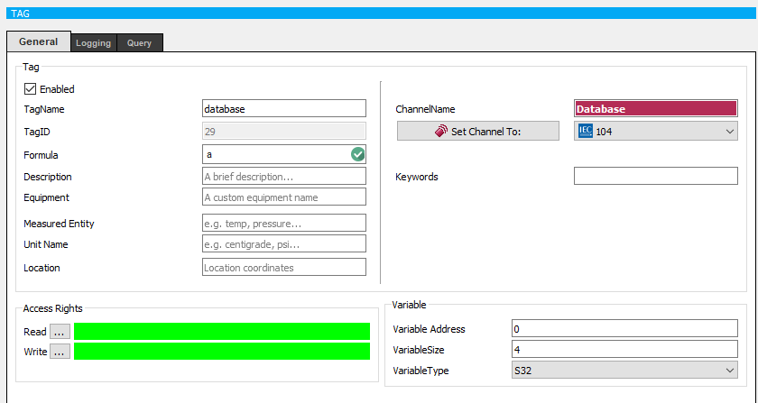
General Tag Parameters
In Use
Tag is ignored by the SCADA server if the tag is not marked as "in use". The tag only becomes a definition in the system.
Tag Name
Each tag must have a unique name. Clear words and format should be used to describe the tag briefly
Description
Give a brief description about the tag
Unit Name
This is an optional property for the tag. It may be useful if you want to group tags by units on the field
Tag Type
This is an option for selecting "Schedule Tag" which is a special register reserved for calendar operations on Mikrodev devices. For more details see Mikrodiagram documentation
Access Rights
Reading: These are the rights that users have to have in order to see the tag values. Users who do not have the rights set here will not be able to read this tag value. Writing: It is the right that users have to have in order to change tag values. Users who do not have the rights set here can not change this tag value.
Variable
Variable Type: The mathematical type of the variable.
Logging
Log to Database
If this option is not enabled, the tag value will not be logged on the system and historical values will not be visible. Also, historical values can not be viewed on the graph.
Log on change
Logging is done in case of tag value change. The type of change can be of the type "Percentage" or "Level" change.
Percentage Change
If "Percentage Change" is selected as the type of change; Logging is done if the tag value changes by the specified percentage value of the latest logged value. If value is set to "0", all kinds of changes are logged.
Level Change
If "Level Change" is selected as the type of change; if the tag value has changed by the specified value, logging is done. If value is set to "0", all kinds of changes are logged.
Log Periodically
If this option is enabled, the tag is continuously logged in the specified time period. Note: Logging type and tags to be logged must be carefully selected to avoid unnecessary increase in the size of the data to be stored. For example;
The tags should never be logged if you do not need historical values. If a level or percentage change is selected for analog variables, a percentage or level appropriate to the data exchange pattern should be selected. For digital values, "log on change" should be used instead of periodic logging.
Data Logging Filter
By using the data logging filter, you can prevent the measurement values ??collected from the field from being logged according to the filter you selected. So, you will be able to pick up possible false data
Only log when decreasing by maximum This filter only allows logging of descending data below the entered maximum value. For example; If the maximum value is entered as 1000:
188,
225 ,(logged)
1500,(not logged)
350 ,(logged)
400  (logged)
In this example, the value '1500' is 1275 more than the previous value, so it exceeds the maximum value of 1000. Thus, is not logged.
Only log when increasing by maximum This filter only allows logging of incremental data below the maximum value entered.
Only log if value is in range This filter allows logging only if the value read from the field is in the specified range.
Only log if value is out of range This filter allows logging only if the value read from the field is out of the specified range.
Alarms
Alarms are an integral part of monitoring systems. ViewPLUS can create alarms for users according to field data and user's access rights.
Creating Alarms
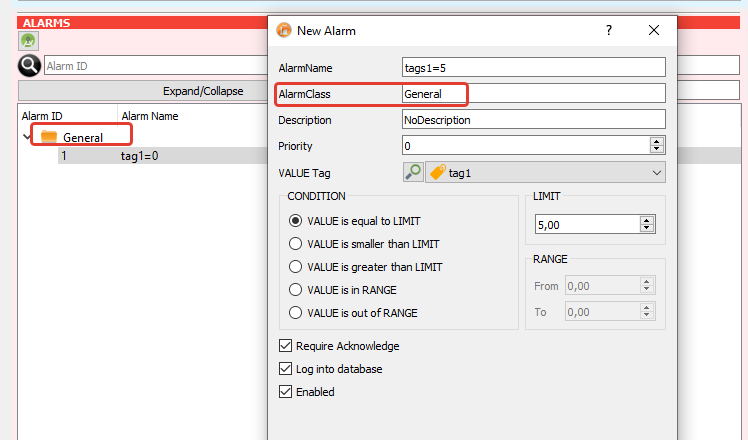
To create an alarm, open "Tag/Channel Editor Panel". Alarms pane is on the bottom left of the screen. Right click on alarm pane. On the context menu select "New Alarm" action.
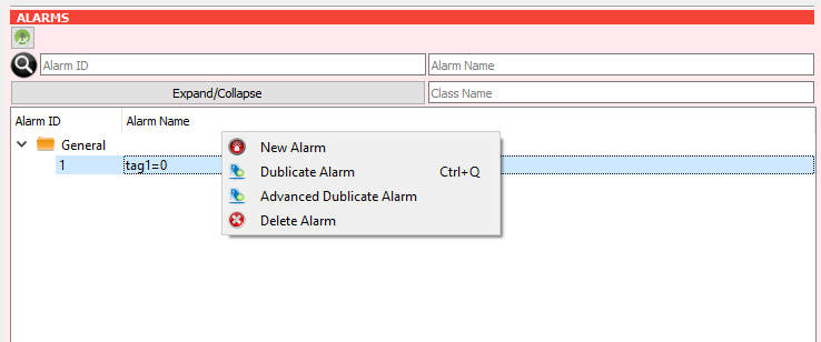
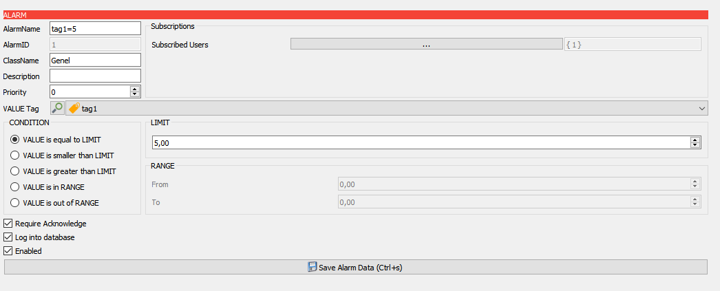
On the "New Alarm" dialog write a name and description for the alarm. If you write an existing "class name" into Alarm Class, the alarm will be added to that class; if you write a new "class name" a new Alarm Class will created and the alrm will be added to that class.
General Alarm Parameters
Alarm Name : Give an apparent unique name for the alarm
Class Name : The name of the class which the alarm belongs to. This is useful when grouping the alarms
Description : In order to make the generated alarms more understandable, definitions are made here
Priority : 4 different definitions can be made according to the priority order of the alarms. In order to see the priority ranges allocated for definition, it is necessary to move the mouse to this part.
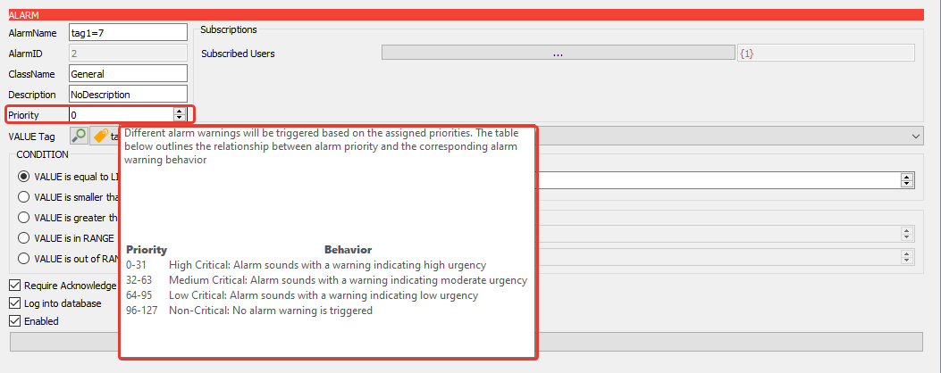
The alarms on the client screen can play in three different alarm sounds based on their priority level.
The priority levels for high-level alarms range from 0 to 31,
For medium-level alarms range from 32 to 63,
For low-level alarms range from 64 to 95,
For warning alarms specifically added, the priority level ranges from 96 to 127.
What sets warning alarms apart from other alarms is that when an alarm condition occurs, they do not play an alarm sound. Instead, they operate as silent alarms.
Note : 4 different alarm definitions according to priority level are valid for ViewPLUS SCADA version 0.9.154 and later. Previous versions do not have this feature.
Value Tag : The selected tag is the source of the alarm. Condition check will be made on this tag's value.
Condition : The conditions are evaluated according to the LIMIT and RANGE values on the right side of conditions pane
- VALUE is equal to LIMIT
The alarm is activated if the value of the tag is equal to "LIMIT" value. - VALUE is smaller than LIMIT
The alarm is activated if the value of the tag is smaller than "LIMIT" value. - VALUE is greater than LIMIT
The alarm is activated if the value of the tag is greater than "LIMIT" value. - VALUE is in RANGE The alarm is activated if the value of the tag is in RANGE.
- VALUE is out of RANGE
The alarm is activated if the value of the tag is out of RANGE.
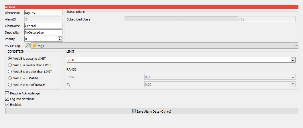
Subscriptions : Alarms must be assigned to users so that they can be viewed on the Client screen. A user can only monitor the alarm to which he is subscribed.
Click on the three dots next to Subscribed Users to add a user subscription to the alarm.
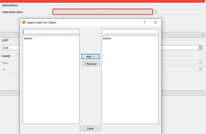
On the opened dialog, select the users which you want to be subscribed on the alarm.
Other
Require Acknowledge : When this option is checked, if the user does not acknowledge the alarm, the alarm will not disappear from the Client screen alarms page even if the alarm condition disappears.
Log into Database : When this option is checked, the alarm states will be logged into database
Enabled : The alarms generated by this option are enabled or disabled.
For detailed information: Alarm Identification and E-mail Sending.
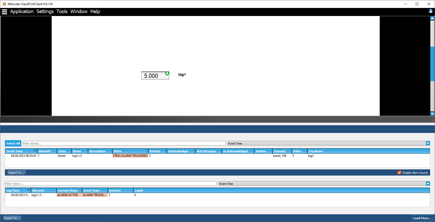
Monitoring Alarms
Alarm states prepared through the editor can be monitored not only from the alarms tab on the client or server screen but also from the SCADA design pages.
To monitor alarm states from the client or server screen, refer to the ViewPLUS SCADA Alarm Pages Application Note document.
Monitoring Alarm States on SCADA Design Pages
Alarm labels can be associated with SCADA components added to SCADA design pages, allowing the alarm status of the label to be tracked through the components. Furthermore, alarm statuses monitored through SCADA components can be acknowledged by generating acknowledgment messages via the components.
SCADA Component Alarm Application
Create a new SCADA project and define labels.
Create alarm states for the defined labels.
- Open the SCADA Editor page, add one of the SCADA components to the SCADA design page to monitor the alarm states of the label.
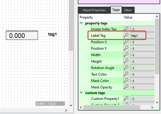
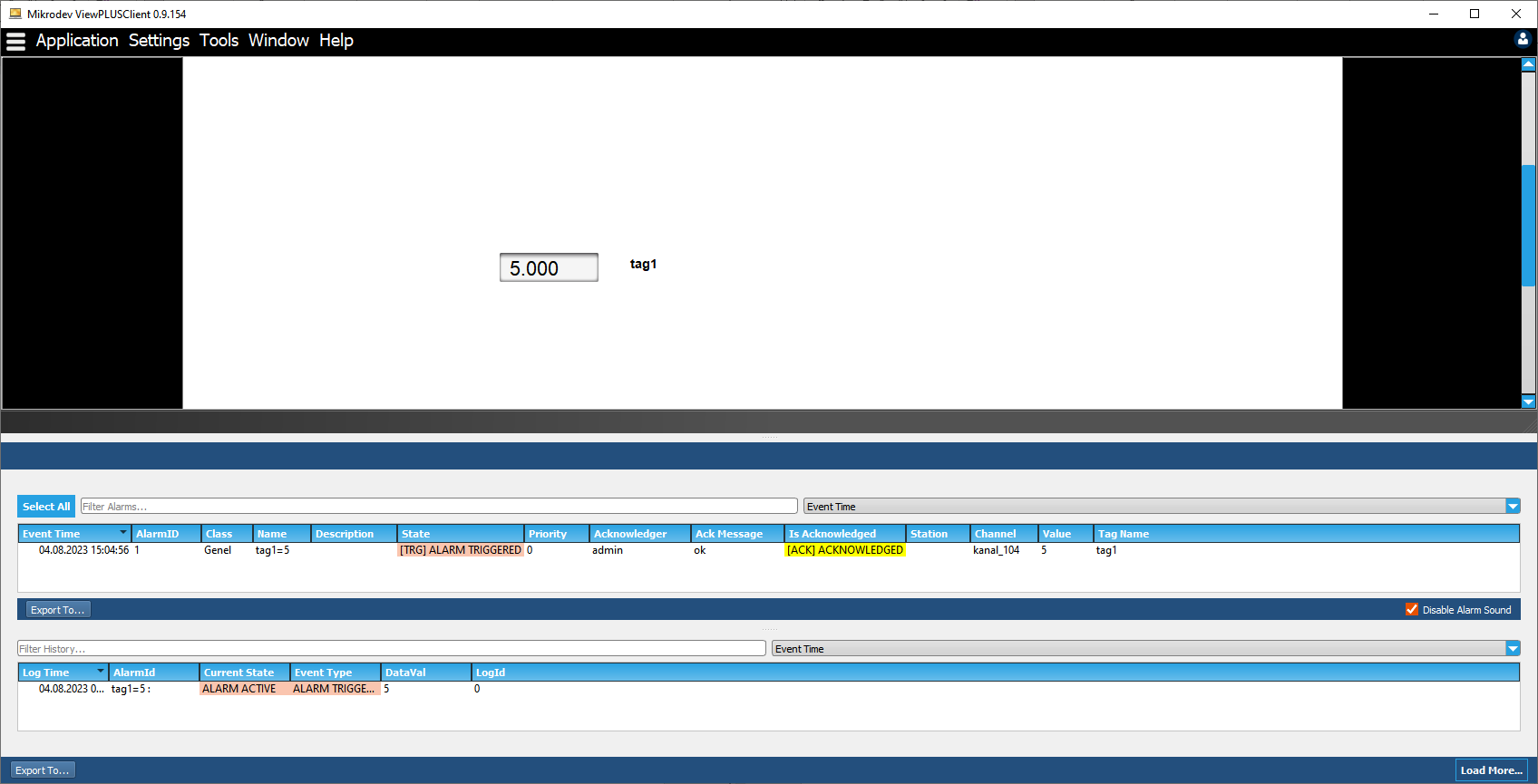
In this example, to monitor the value of label 1 in the SCADA, a display was added to the page, and the label 1 was selected from the text label section.
- To monitor alarm states through the added component, click on the component, locate the Events section in the properties panel on the right side. Check the option "Show Alarms" located here.
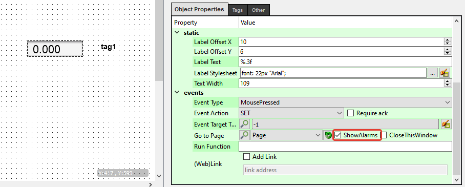
Start the server and then open the client application.
When an alarm value is sent to the label associated with the SCADA component, you will observe that a bell icon appears on the component, and the alarm icon changes color, flashing on and off.
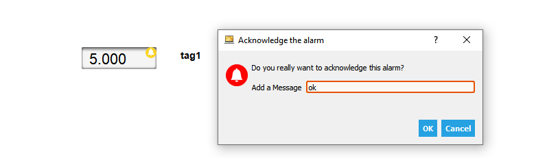
- Right-click on the bell icon to acknowledge the alarm. As a result of this action, you will see the option to acknowledge the alarm.

- Click on the "Acknowledge Alarm" text, and in the opened window, add an acknowledgment message to the alarm.
- After confirming the alarm status, you will observe that the bell icon on the SCADA component disappears.
SCADA Page Alarms Application
Create a new SCADA project and define labels.
Create alarm states for the defined labels.
Open the SCADA Editor page. Create two separate pages: one for the homepage and the other for displaying alarm statuses using SCADA components.
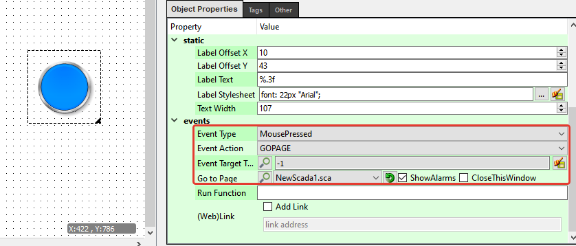
To transition from the homepage to another page, select the button icon from within the SCADA components and add it to your SCADA page.
Click on the button icon. On the right side, find the Events section in the object properties. Select event type "Mouse Button Down," event action "Go Page," and from the "Go Page" section, choose the other page you created. To monitor alarm states through the button, the "Show Alarms" option should be checked.
- To monitor the alarm states of the label, add one of the SCADA components to the SCADA design page that is navigated using "Go Page" from the homepage.
In this example, to monitor the value of label 1 through SCADA, a display was added to the page, and label 1 was selected from the text label section.
Start the server, and then open the client application.
When an alarm value is sent to the label associated with the SCADA component, observe that an exclamation mark icon appears on the button and flashes on and off.
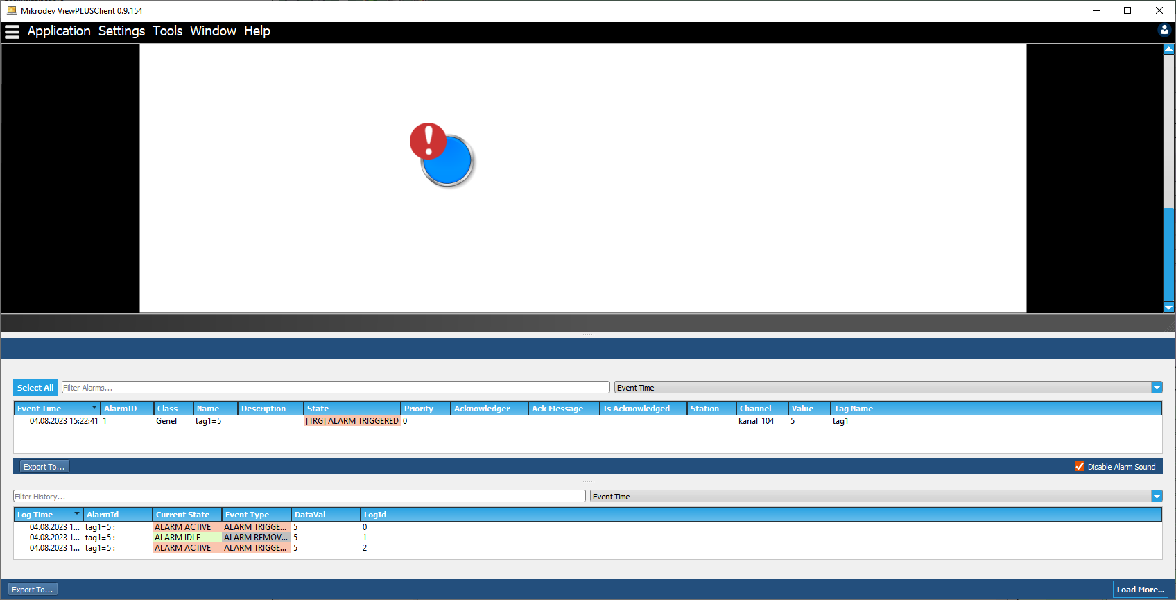
Note: Alarms cannot be acknowledged from the exclamation mark icon displaying page alarms.
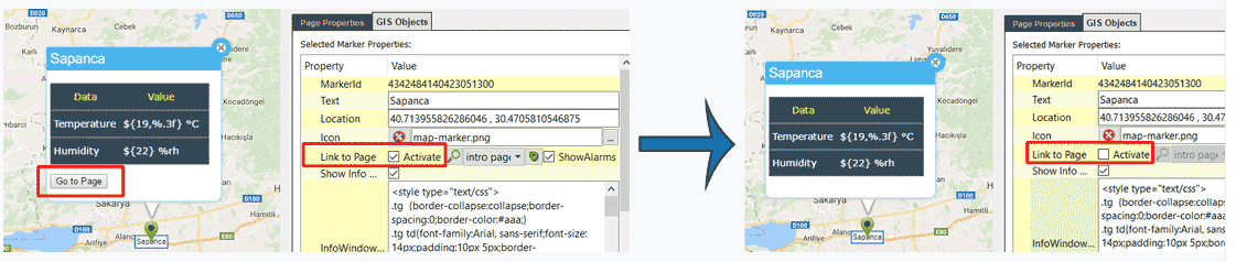
Create a new SCADA project and define labels.
Create alarm states for the defined labels.
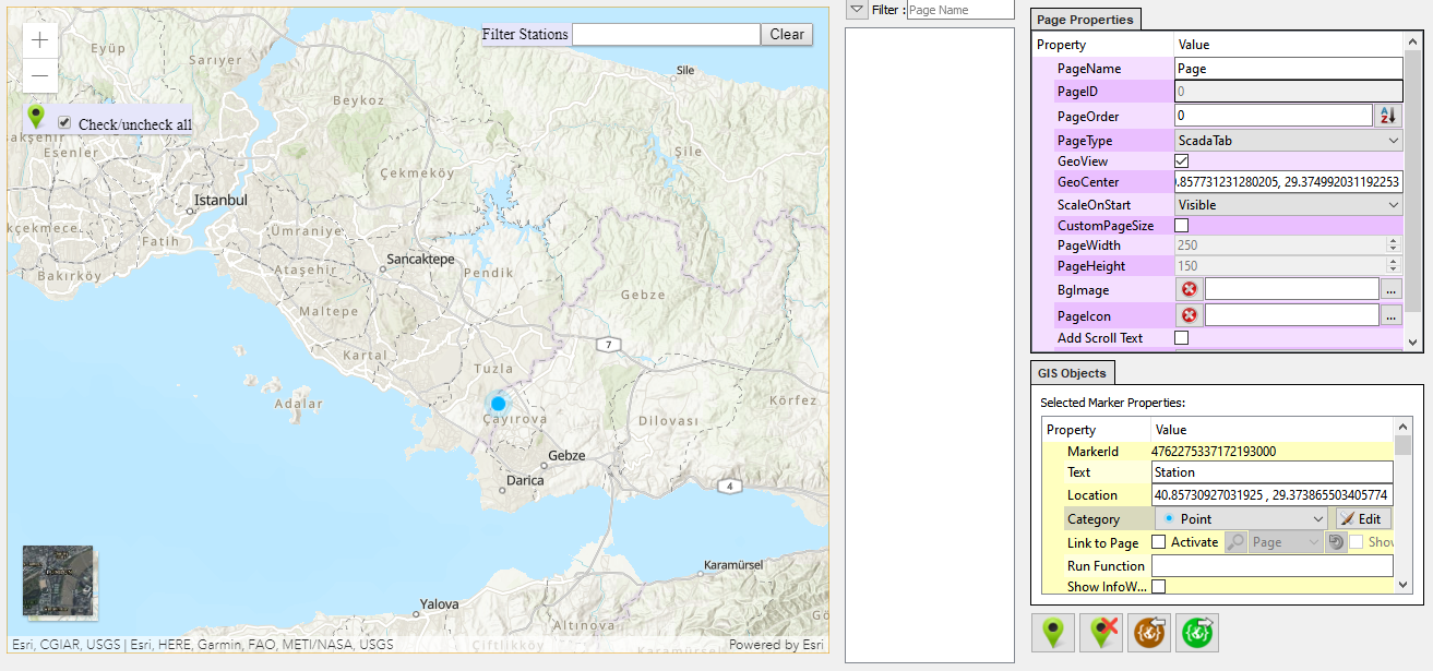
The map page uses "Go to Page" event action with location markers. Therefore, as in the previous example, page alarms will be created. Prepare two separate pages for the map page and the page where alarm statuses will be associated.
Open the SCADA Editor page. To set the opened page as a map page, check the geo view option in the page properties. Click here to get detailed information about map pages.
- Add location markers to the map page. Click on the marker under the GIS objects section and place it on the desired location on the map.
- Click on the added location marker on the page. Under the GIS objects section, check the "Active" option next to the "Link to Page" section and select the other page where alarm statuses will be associated. To monitor alarm statuses through the location marker, the "Show Alarms" option should be checked.
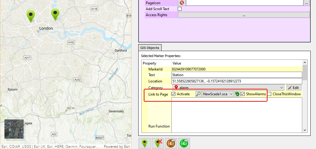
- To monitor the alarm states of the label, add one of the SCADA components to the SCADA design page that is navigated using "Go Page" from the map page.
Start the server, and then open the client application.
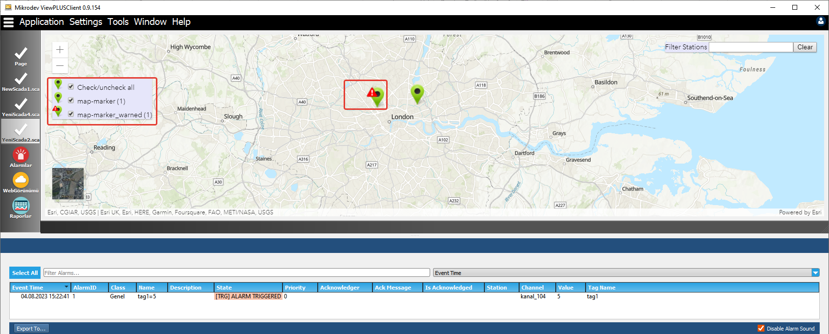
When an alarm value is sent to the label associated with the SCADA component, you will observe that an exclamation mark icon appears on the location marker, and in the top left corner of the client screen, you will see the number of location markers in alarm.
Associating PLC and SCADA Projects
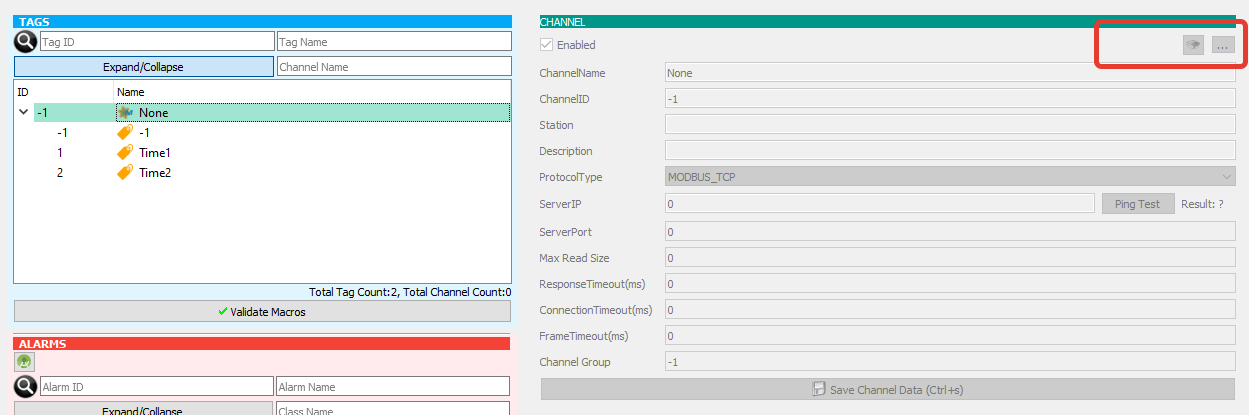
As you develop your project, it becomes more important to associate channels in SCADA with PLC projects to avoid confusion.To do this, you can specify the PLC project path in the upper right corner of the channel menu.
Import and Export Operations
There are different options for importing/exporting data from/to the project.
Importing/Exporting Projects
This wizard allows the user to import/export tags, channels, alarms, users and pages using a special file format(.scaexp).
Exporting Project
After opening the project on ViewPLUS, on the File menu select "Export Project" option:
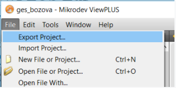
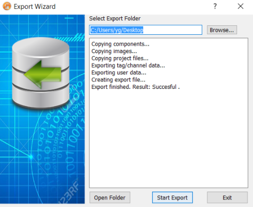
On the wizard window, select an output folder path for the ".scaexp" file to be generated. After that, when you push on the "Start Export" button, the wizard will create the ".scaexp" file
Importing Project
On the File menu select "Import Project" option:
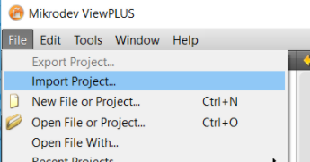
On the wizard window, select the exported ".scaexp" file and a destination folder for the project files to be extracted:
After that, when you push on the "Import Project" option, the wizard will ask for database connection settings. The project database will be extracted into the configured database.
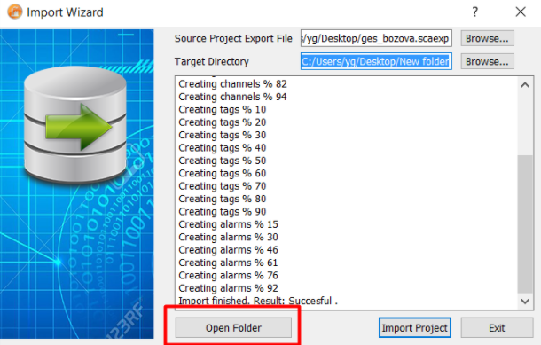
When the operation is complete succesfully, the project is ready to be used.
Importing/Exporting Tags/Channels/Alarms
Users can import/export tag/channel/alarm definitions from/to other projects.
Exporting Tags/Channels/Alarms
After opening the project on ViewPLUS, on the Tools menu select "Export Tag/Channel Definitions" option:
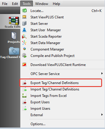
When you confirm the export file path selection dialog, a file with ".tcf" extension will be created. You can use this file for importing into other projects.
Importing Tags/Channels/Alarms
After opening a project on ViewPLUS, on the Tools menu select "Import Tag/Channel Definitions" option:
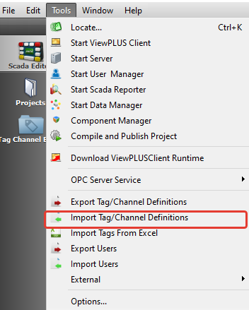
Important Note: This operation will overwrite existing tags. Thus, this operation may damage your project. Be sure that the exported tag id interval and local project's tag id interval do not intersect!
Importing/Exporting Users
Users created for a project could be exported to another project. Export/Import users menu could be used for that
Exporting Users
After opening the project on ViewPLUS, on the Tools menu select "Export Users" option:
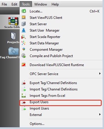
When you confirm the export file path selection dialog, a file with ".usr" extension will be created. You can use this file for importing users into other projects.
Importing Users
After opening a project on ViewPLUS, on the Tools menu select "Import Users" option:
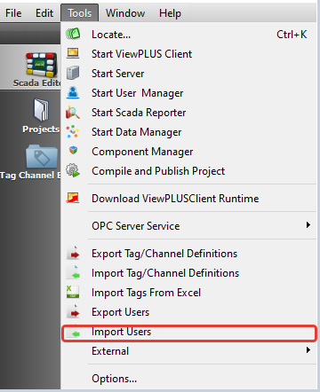
Important Note: This operation will overwrite existing users. Thus, this operation may damage your project. Be sure that the exported user id interval and local project's user id interval do not intersect!
-For detailed information: Channel and User Definitions.
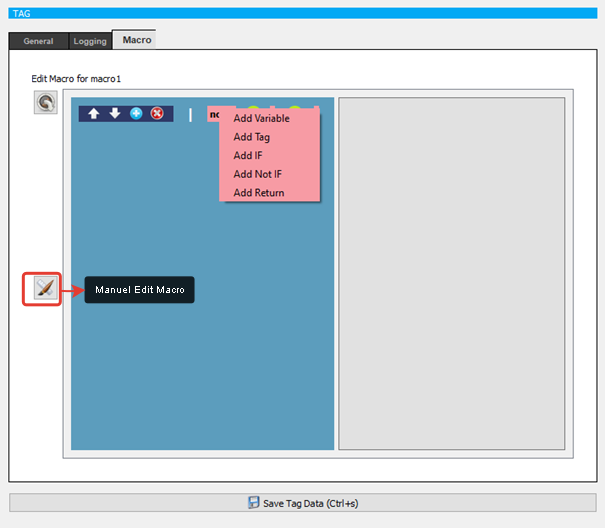
Macro Guide
ViewPLUS supports macros in different types. Some of these macros work on the server side, while others work on the client side.
The "macro tags" we define in the Tag/Channel Editor work on the server side. And it acts as a virtual tag. These macros work continuously on the server for the specified period.
On the editor, it is possible to write separate macros for each object. These macros affect the display and behavior of that object and are only executed when the user is watching the object.
Server Side Macro Tags
Macros can take two processing elements at a time and are written line by line.
Example:
[ v0 = $1234 * 2]
The operands that can be inserted into the macro are:
200 seperate variables(vo, v1, …., v199)
Tag values (in "$1234" format)
Constant values (Constant decimal values such as "234,12" can be added)
[ v0 = $1234 * 2]
v0 : The element to the left of “ = ” is the final result of the operation
- : Operators like “+ , - , * , / , % , & , |, ^ , > , < , e ,b , k , n , ?“ could be used. Here:
e: Equality check. The result is "1" if the operands are equal to each other, and "0" if not..
n: Not equal check. If the operands are not equal to each other, the result is "1", otherwise it returns "0".
b: Greater than check. If the first operand is greater than the second, the result is "1", otherwise it returns "0".
k: less than check. The result is "1" if the first operand is smaller, and "0" if it is not.
?: This is a special operand.
[ v0 = 1234 ? 0] : Returns the "RX Count" value of the tag with id 1234 (Read counter value)
[ v0 = 1234 ? 1] : Returns the "Read Time" value of the tag with id 1234 (the time at which the latest data was read from the field)
[ v0 = 1234 ? 2] : Checks whether there is communication with the device on which the tag with id 1234 is located
[ v0 = 1234 ? 3] : Checks whether there is a valid value in the tag with id 1234.(In general, when a SCADA server is started for the first time, it may be late to write a valid value in the tag, or a valid value of the tag may never be written)
[ v0 = v0? 20] : Writes server datetime into "v0" variable as the number of seconds that have passed since 1970-01-01T00:00:00
[ v1 = v0? 21] : Writes server year into "v1" as "v0" is the number of seconds that have passed since 1970-01-01T00:00:00
[ v2 = v0? 22] : Writes server month into "v2" as "v0" is the number of seconds that have passed since 1970-01-01T00:00:00
[ v3 = v0? 23] : Writes server day into "v3" as "v0" is the number of seconds that have passed since 1970-01-01T00:00:00
[ v4 = v0? 24] : Writes server hour into "v4" as "v0" is the number of seconds that have passed since 1970-01-01T00:00:00
[ v5 = v0? 25] : Writes server minute into "v5" as "v0" is the number of seconds that have passed since 1970-01-01T00:00:00
[ v6 = v0? 26] : Writes server seconds into "v6" as "v0" is the number of seconds that have passed since 1970-01-01T00:00:00
Attention: Here the tag id (1234 in the example) must be entered into the macro as a fixed value without "$" at the beginning
Condition check:
In the following example, it is checked whether the variable "v0" is equal to 1. If "v0" is equal to 1, the macro executes the command on the bottom line (makes v1 value 555). If it is not equal to 1, the line is moved down by the second parameter ("2") of the "IF" line. In this example, if "v0" is not equal to 1, the macro will go down 2 lines, that is, it will go to the return value ([E]) line and it will be finished.
[ IF , v0 , 2]
[ v1 = 555]
[ E ]
Another condition control operand is “NI” (NOT IF) . This checks the equality to 0 as the opposite of "IF"..
In the following example, it is checked whether the variable "v0" is equal to 0. If "v0" is equal to 0, the macro executes the command on the bottom line (makes v1 value 555). If it is not equal to 0, the line is down by the second parameter ("2") on the "NI" line. In this example, if "v0" is not equal to 0, the macro will go down 2 lines, that is, it will go to the return value ([E]) line and it will finish
[ NI , v0 , 2]
[ v1 = 555]
[ E ]
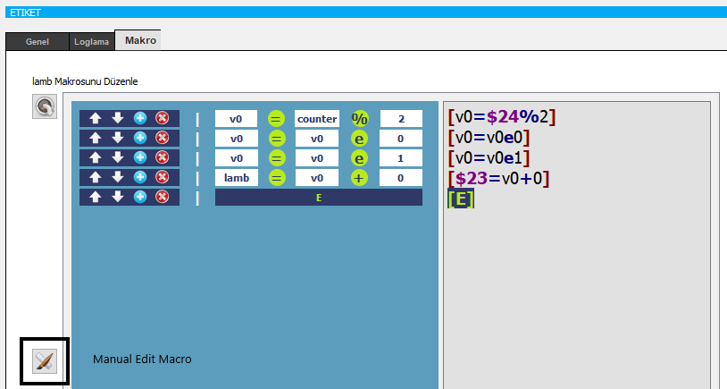
In order for macros to work correctly , a return ([E] </ nowiki> return) must be added.
Client Macros
Client Macros: This macro is written in the same format as the "server macros". However, only tags defined on that object can be used within those macros The tags defined on the tag tab of objects are used as follows:
For each tag "i, o, s, w" values exist.
i (in) : The raw value of the tag read from the field
o (out):The value to display on the screen after the tag has been passed through the macro operations
s (set):The value set by the user for the tag
w(write): The value to be written to the field device after the value that the user wants to set is passed through the macro operations
i ---Macro---->o , s---Macro---->w
If there is no macro operation 'i' is equal to 'o', 's' is equal to 'w'.
Macros can take two processing elements at a time and are written line by line.
Example:
In the example below, the variable "v0" takes the value of the tag 123 and then its value is checked. If "v0" is equal to 1, the macro executes the command in the bottom line (making o1 a 1). If not equal to 1, the line is shifted down by the second parameter of the "IF" line ("2"). In this example, if "v0" is not equal to 1, the macro will go down 2 lines, ie the return value ([E]) line, and finish.
[ v0 = $123 ]
[ IF,v0,2 ]
[ o1 = 0+1 ]
[ E ]
The value of the variable "o1" is checked. If "o1" equals 1, the macro executes the command on the bottom line (writes o1 as 1). If not equal to 1, the line is shifted down by the second parameter of the "IF" line ("2"). In this example, if "v0" is not equal to 1, the macro will go down 2 lines, ie the return value ([E]) line, and finish.
[ IF,o1,2 ]
[ w1=0+1 ]
[ E ]
To learn the sequence numbers of the labels for o, i, s, w, simply move the pointer over it.
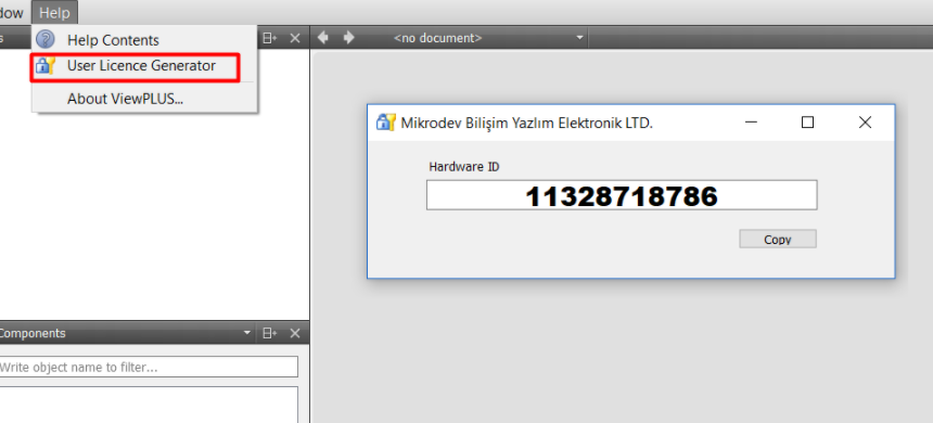
Installing the License File
To get a valid license please send your "hardware id" to [email protected]. To learn your hardware id; select Help > User License Generator from the application menu.
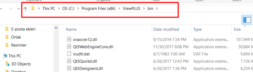
After you receive a valid "license.dat" file, copy this file into bin folder of ViewPLUS application
The licence will automatically be loaded when you restart the Editor
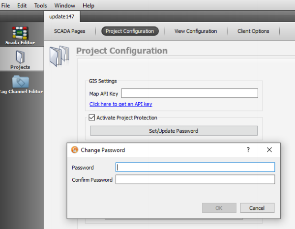
Project File Password
The password can be used to make the project more reliable. In order to set a password to the project, activate project protection is marked by entering the project configuration from the projects tab. Password should contain upper, lower letters, numbers ans symbols. The password should have more than 8 characters.
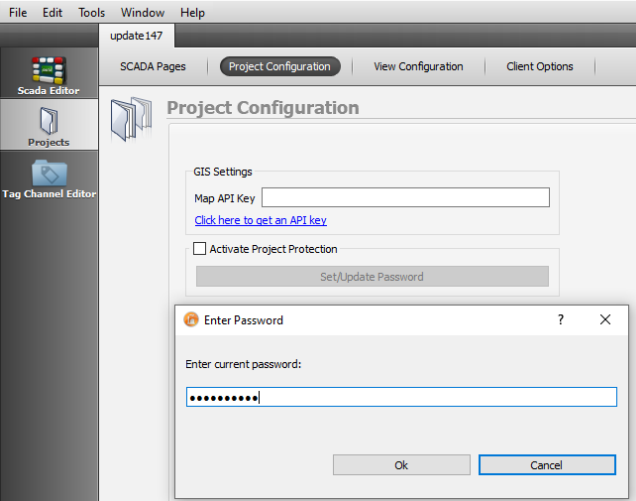
To remove the project file password, the activate project protection is removed and the current password is entered.
ArcGIS Map
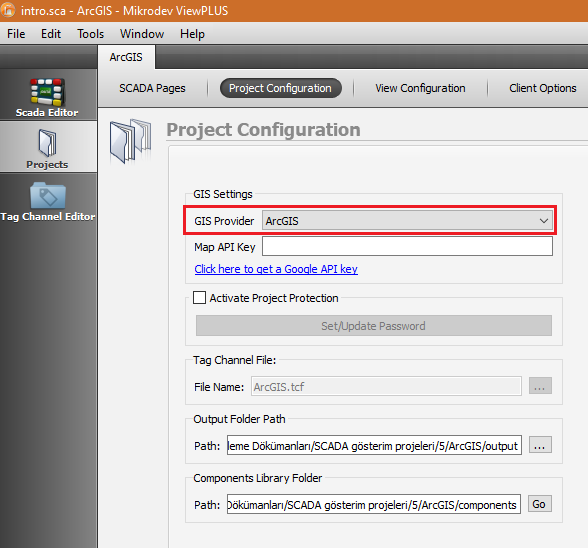
ArcGIS technology is a scalable integrated Geographic Information System software that developed by ESRI. Software components are built on the common library of ArcObjects. That provides a system. In order to use the ArcGIS map, ArcGIS must be selected from the Projects menu under GIS settings.
ArcGIS map is activated when the "GeoView" parameter is selected from the Page Properties menu on the right side of the page. The "GeoCenter" parameter shows the location of the marker on the map. It should be in the form of longitude and latitude. Markers can be added on the map with the using marker icon under the "GIS Objects" menu or the markers added on the map can be deleted by using delete marker icon.
Marker icons can be changed by creating new categories and markers can be grouped under a category.
To create a new category, click the Edit button in the Category line from the GIS Object menu. In the window that opens, click "Add New Category" and define "Category Name" and "Category Image".

Marker is selected and then Category part of GIS Object, we select the point as new category. Hence icon and category selection are completed.
ViewPLUS SCADA Channels
Channel: Modbus TCP
You must create a new Modbus Channel to communicate with field devices over TCP using ModBus protocol.
Select "Modbus TCP" as the "Protocol Type" in the dialog for creating a new channel.
For detailed information: Modbus TCP Definitions.
Max. Read Size
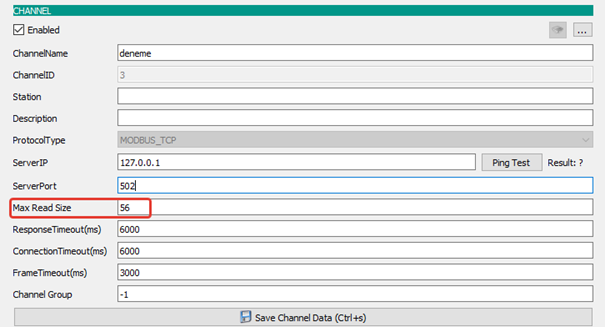
There is a "Maximum Reading Size" field in the Channel section of the Label Channel Editor tab in ViewPLUS.
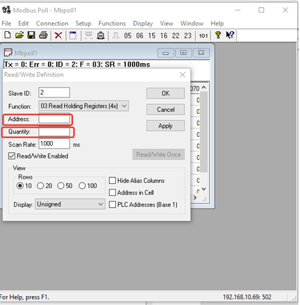
Modbus Protocol supports read/write up to 125 registers for modbus address.
Channel Parameters
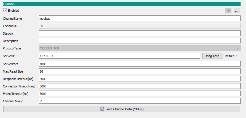
Server IP
The IP address of the device you want to connect to
Server Port
Modbus connection port information of the device
Response Timeout
It is time value, the Modbus slave waiting for the device to respond after each modbus request, in milliseconds. If no response is received from the slave device during this time, a new request is sent.
Connection Timeout
It is the time value in milliseconds to wait until a new connection attempt is made after the request to connect to the device is sent. Typically in GPRS or 3G networks this time may be slightly longer than TCP.
Frame Timeout
It is the time value in miliseconds to be waited until the next request is sent, after receiving a response from a Modbus request.
Tag Parameters
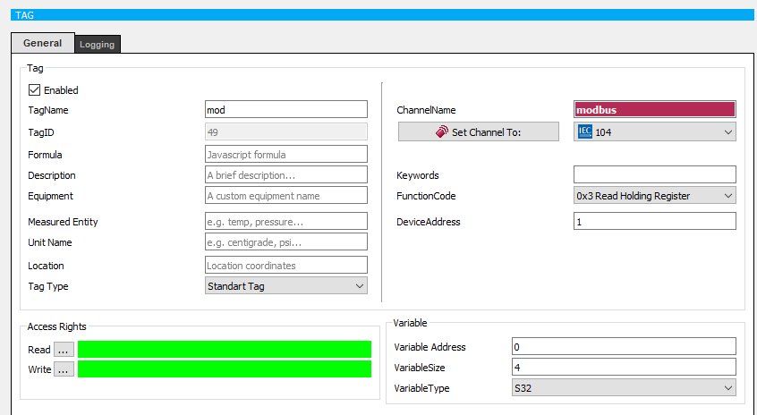
Function Code
The IP address of the device you want to connect to
Device Address
Modbus protocol device address
Variable Address
Modbus variable address
Variable Size
The size of the variable in the identified address
Variable Type
The type of the variable in the identified address
Channel: IEC 104
You must create a new IEC 104 Channel to communicate with the field devices over TCP using the IEC 104 protocol.
Channel Parameters
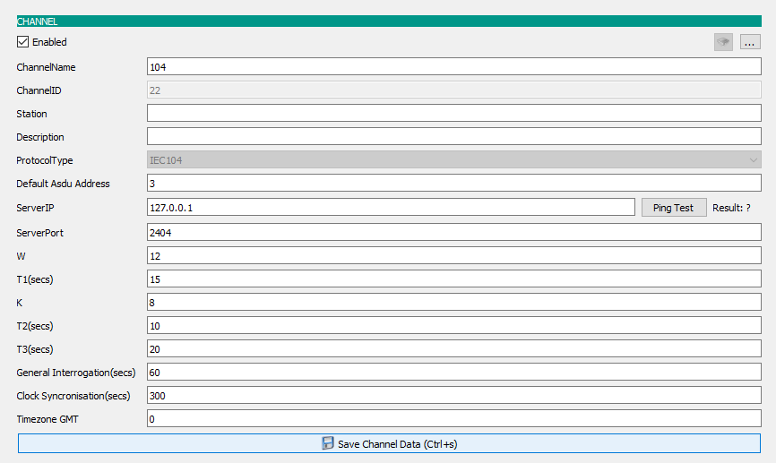
Server IP
The IP address of the device you want to connect to
Server Port
IEC 104 connection port information of the device
W
ACK(acknowledge message) sending frequency(sends ACK after W packets)
K
The maximum allowed number of unacknowledged packets
T1
ACK timeout duration for ASDU packet
T2
If no new data will be sent after this time, an ACK is sent
T3
Timeout period for test frame
General Interrogation
General Interrogation message sending frequency
Clock Synchronisation
Clock Synchronisation message sending frequency
Timezone GMT
Timezone information of server computer
Tag Parameters
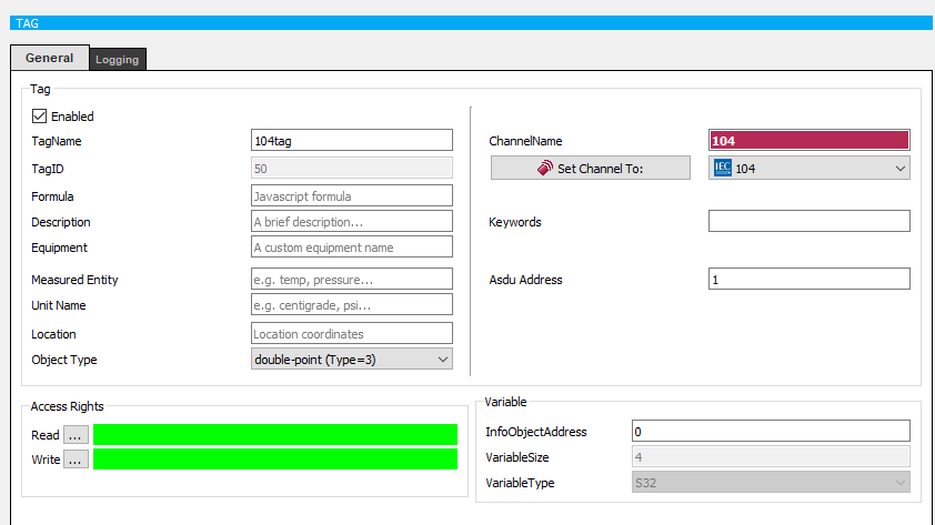
ASDU Address
RTU specifies the address where the device will communicate over IEC 104.
Object Type
IEC 104 Adress List:
- Single-point information (Type=1)
- Double-point information (Type=3)
- Step position information (Type=5)
- Bitstring of 32 bit (Type=7)
- Measured value, normalised value (Type=9)
- Measured value, scaled value (Type=11)
- Measured value, short floating point number (Type=13)
- Integrated totals (Type=15)
- Packed single point information with status change detection (Type=20)
- Measured value, normalized value without quality descriptor (Type=21)
- Single-point information with time tag CP56Time2a (Type=30)
- Double-point information with time tag CP56Time2a (Type=31)
- Step position information with time tag CP56Time2a (Type=32)
- Bitstring of 32 bit with time tag CP56Time2a (Type=33)
- Measured value, normalised value with time tag CP56Time2a (Type=34)
- Measured value, scaled value with time tag CP56Time2a (Type=35)
- Measured value, short floating point number with time tag CP56Time2a (Type=36)
- Integrated totals with time tag CP56Time2a (Type=37)
- Event of protection equipment with time tag CP56Time2a (Type=38)
- Packed start events of protection equipment with time tag CP56Time2a (Type=39)
- Packed output circuit information of protection equipment with time tag CP56Time2a (Type=40)
- Single command (Type=45)
- Double command (Type=46)
- Regulating step command (Type=47)
- Set-point Command, normalised value (Type=48)
- Set-point Command, scaled value (Type=49)
- Set-point Command, short floating point number (Type=50)
- Bitstring 32 bit command (Type=51)
- Single command with time tag CP56Time2a (Type=58)
- Double command with time tag CP56Time2a (Type=59)
- Regulating step command with time tag CP56Time2a (Type=60)
- Measured value, normalised value command with time tag CP56Time2a (Type=61)
- Measured value, scaled value command with time tag CP56Time2a (Type=62)
- Measured value, short floating point number command with time tag CP56Time2a (Type=63)
- Bitstring of 32 bit command with time tag CP56Time2a (Type=64)
- Interrogation command (Type=100)
- Counter interrogation command (Type=101)
- Read command (Type=102)
- Clock synchronisation command (Type=103)
- Reset process command (Type=105)
InfoObjectAddress
From the RTU device to be read, the address information of the label is entered.
Channel: DNP3
You must create a new DNP3 Channel to communicate with the field devices over TCP using the DNP3 protocol.
Channel Parameters
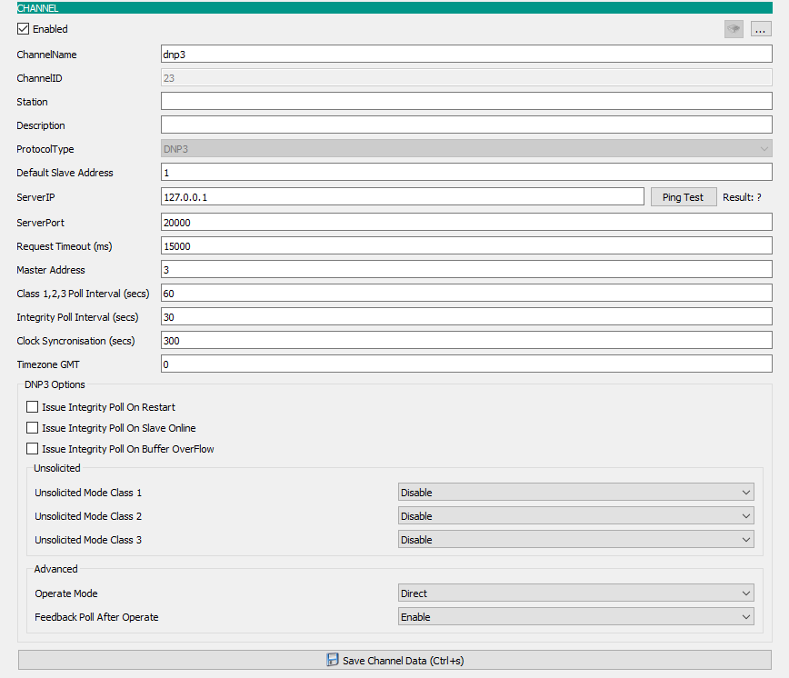
Server Port
DNP3 Server Port default 20000.
Clock Synchronisation
Clock Synchronisation message sending frequency.
Timezone GMT
Timezone information of server computer.
Request Timeout
Indicates the frequency with which the server receives a request message.
Class 1,2,3 Poll Interval(secs)
It sends seperate queriesto the classes at sspecified time intervals.
Integrity Poll Interval(secs)
It performs the query as a whole at specified time intervals.
Tag Parameters
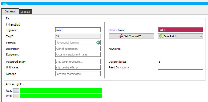
Channel: SNMP
This channel is used to connect to SNMP devices. The NetSnmp library must be installed on your system in order for this channel type to work. You can download NetSnmp library from here : Here.
Channel Parameters

Server IP
The IP address of the device you want to connect to.
Server Port
SNMP Server Port default 161.
Tag Parameters
Channel: Macro
This channel is used to create virtual tags and modify them with scripts.
For detailed information: Macro Channel Definitions.
Channel Parameters

Frame Timeout
The time in milliseconds that expresses the frequency of operation of the macro.
Tag Parameters

- "+" : Add
- "-" : Substract
- "*" : Multiply
- "/" : Divide
- "%" : Modding
- "&" : Logical and operation
- "|" : Logical or operation
- "?" : Special operand
- "^" : Logical private or operation
- ">" : is greater than
- "<" : is less than
- "e" : Equal to
- "b" : More than or equal to
- "k" : Less than or equal to
- "n" : Not equal to
Channel: Database
This is the type of channel used to make queries from SCADA's own database. By creating a database channel in ViewPLUS SCADA, operations are performed on the database where the server is running. This is done by writing a query to the tags created under the channel. Queries are entered into the query window. The answers to the query are still displayed in the same label.
Channel Parameters

Response Timeout
The number of milliseconds that represents the frequency at which the database query is executed.

Select data_value from logs.tag_log where tag_id=1 order by logtime  desc limit 1  \\  Indicates the last value for tag_id=1.
Select data_value from logs.tag_log where tag_id=1 order by logtime  limit 1 \\  Indicates the first value for tag_id=1.
Select*from logs.tag_log \\ Shows all values.
For detailed information: Database Channel Definitions.
Channel: Global Database
It is the type of channel used to connect to different databases to create custom queries and to pass these query results to project tags.
Channel Parameters
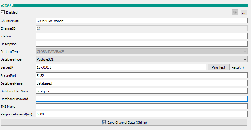
Response Timeout
The number of milliseconds that represents the frequency at which the database query is executed.
Tag Parameters
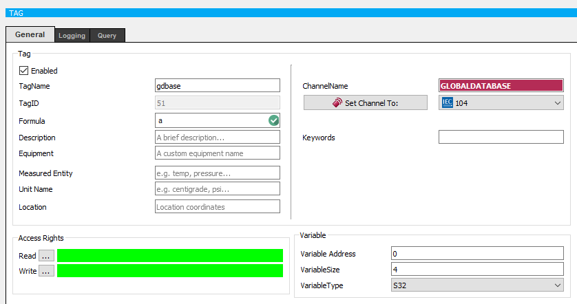
Query
The query expression to be executed in the database. This tag allows retrieving the first line returned from the query. The return values ??for this first row are written into tags respectively into the tags defined in the form of :{${32}, ${33} , ${34}, ${35},....}: An example "Query" expression:
 WITH
 t1 AS (
  SELECT  data_value from logs.tag_log where tag_id=19 AND data_value IS NOT NULL ORDER BY logtime DESC limit 1 ),
 t2 AS (
  SELECT  data_value from logs.tag_log where tag_id=20 AND data_value IS NOT NULL ORDER BY logtime DESC limit 1),
 t3 AS (
  SELECT  data_value from logs.tag_log where tag_id=29 AND data_value IS NOT NULL ORDER BY logtime DESC limit 1),
 t4 AS (
  SELECT  data_value from logs.tag_log where tag_id=26 AND data_value IS NOT NULL ORDER BY logtime DESC limit 1)

 SELECT t1.data_value data1, t2.data_value  data2, t3.data_value  data3, t4.data_value  data4
 FROM t1, t2 ,t3,t4;

 :{${32}, ${33} , ${34}, ${35}}:
In the above PostgreSQL database query, the latest recorded database values of the tags 19, 20, 29, and 26 are written into the tags with 32, 33, 34, 35 IDs, respectively.
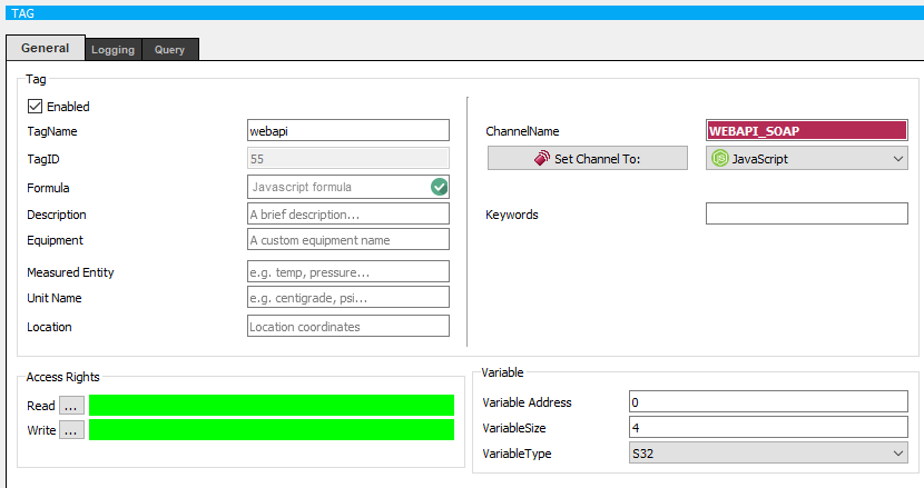
Channel: JavaScript
JavaScript functions could be defined JavaScript channel. You can call various Math functions in your scriptReference. You can also use the values of system tags in the form of "${123}". You need to "return" a numeric value for the function result to be written on the "JavaScript Tag"
Channel Parameters

Response Timeout
The number of milliseconds that represents the frequency at which the JavaScript function is called. Tag Parameters
Query
The JavaScript expression to be called. : An example "JavaScript" expression:
var1 = 5 + ${19};   //In the first  line : define a variable "var1" and assign "the value of tag with id 19" plus "5"
 var2 = 3 + ${20};   //In the second line : define a variable "var2" and assign "the value of tag with id 20" plus "3"
 subtotal= (var1 +var2 );      //In the third  line : define a variable "subtotal" and assign "the sum of var1 and var2" to it
 return Math.sqrt(subtotal);   //In the last   line : evaluate the square root of subtotal and return to that value. The return value will also be written as the value of the current  JavaScript Tag.
IMPORTANT NOTE
You cannot set the values of other system tags in JavaScript tag. You need to use Macros to achieve this. Thus the following script will not work:
${20}= 3 + var1 ;
For detailed information: Javascript Channel Definitions.
Channel: SOAP API
It is the type of channel used to connect to a SOAP Web Service and to pass the query results into project tags.
Channel Parameters

Response Timeout
The number of milliseconds that represents the frequency at which the query is executed. Tag Parameters
Query
The API expression to be send to SOAP service. The query result is parsed and the relevant return values are written into tags: The query expression is composed of 3 parts. The first part identifies the WSDL path of the SOAP server. The second part is the actual SOAP query envelope. And the last part is the tag binding expression for the results to be written into correct tag values. An example "Query" expression:
WSDL_PATH = https://minosxcloud.umpi.it/ws/wsminos.php?wsdl;

<SOAP-ENV:Envelope
    xmlns:SOAP-ENV="http://schemas.xmlsoap.org/soap/envelope/"
    xmlns:ns1="http://localhost/"
    xmlns:xsd="http://www.w3.org/2001/XMLSchema"
    xmlns:SOAP-ENC="http://schemas.xmlsoap.org/soap/encoding/"
    SOAP-ENV:encodingStyle="http://schemas.xmlsoap.org/soap/encoding/">
  <SOAP-ENV:Body>
    <ns1:getStatus>
      <user xsi:type="xsd:string">ws-istanbul</user>
      <password xsi:type="xsd:string">passwordvalue</password>
      <db_name xsi:type="xsd:string">databasename</db_name>
      <id_andros xsi:type="xsd:string">s345dfsad2345asd45fsdfsgds4542345a</id_andros>
    </ns1:getStatus>
  </SOAP-ENV:Body>
</SOAP-ENV:Envelope>

:{${32}, <stato><statopl num="1"><fase1 stato>  ;
  ${33}, <stato><statoingresso num=17 stato> }:
And the response from the server is as following:
<SOAP-ENV:Envelope SOAP-ENV:encodingStyle="http://schemas.xmlsoap.org/soap/encoding/"
    xmlns:SOAP-ENV="http://schemas.xmlsoap.org/soap/envelope/"
    xmlns:xsd="http://www.w3.org/2001/XMLSchema"
    xmlns:xsi="http://www.w3.org/2001/XMLSchema-instance"
    xmlns:SOAP-ENC="http://schemas.xmlsoap.org/soap/encoding/">
    <SOAP-ENV:Body>
        <ns1:getStatusResponse
            xmlns:ns1="http://localhost/">
            <res xsi:type="xsd:string">
                <armadio identificatore="b3e1f32cb0db36ef0fbfaf047074e4d5">
                    <stato>
                        <statoingresso num="16" stato="1">ON Input Andros CMS-EXP 1</statoingresso>
                        <statoingresso num="17" stato="1">ON Input Andros CMS-EXP 2</statoingresso>
                        <statopl num="1">
                            <fase1 stato="0">Line 1 Phase 1 OK</fase1>
                            <fase2 stato="0">Line 1 Phase 2 OK</fase2>
                            <fase3 stato="0">Line 1 Phase 3 OK</fase3>
                        </statopl>
                    </stato>
                </armadio>
            </res>
        </ns1:getStatusResponse>
    </SOAP-ENV:Body>
</SOAP-ENV:Envelope>
The method to write the result of the response into the tags is as follows:
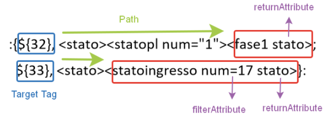
The parser is defined in the form of
:{${tag1 ID}, <child1> <child2>; ${tag2 ID} , <child1> <child2> <child3 filterAttribute returnAttribute> }:
On the last 3 lines of the query, the first parameter is the target tag. The latter part defines how to parse the response. The last element of this part could be used to create an attribute filter for the XML document. The remaining parts are the node hierarchy filter.
If no returnAttribute or filterAttribute is defined, the text value of the node is cast into number and written into tag.
If returnAttribute is defined but no filterAttribute ; the first element of multiple elements is selected and "returnAttribute" attribute's value is returned.
If both returnAttribute and filterAttribute are defined; multiple elements are filtered according to filterAttribute and "returnAttribute" of that node is returned.
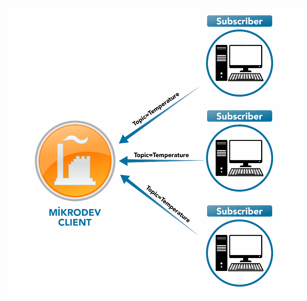
Channel: MQTT Client
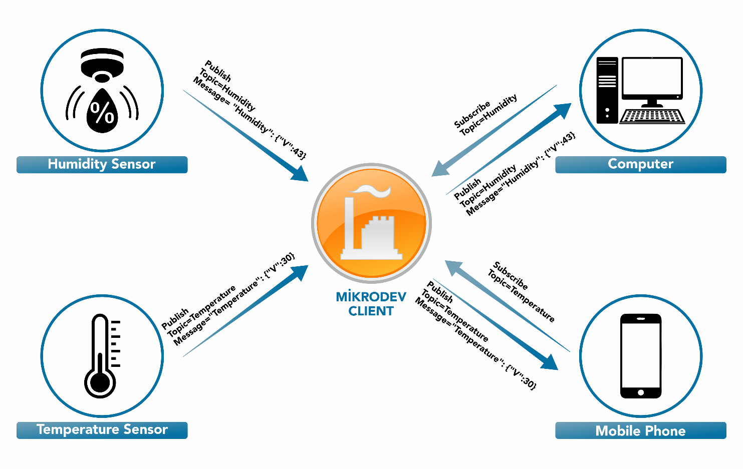
Mikrodev Client receives messages from publisher units and transmits messages to subscribed units. When sending messages, it uses topics to filter client units that will receive the message.
The working structure of Mikrodev Client is described in the picture below.
Mikrodev Client supports the following data types.
| Number | Variable Type |
|---|---|
| 1 | BOOLEAN |
| 2 | DOUBLE |
Structure of Subscriber Unit
Subscribers are units that receive messages according to topics which they inform Mikrodev Client.
Topical names can contain one or more words and numbers. Sample topi-cal names can be listed as below.
| Number | Topical Names |
|---|---|
| 1 | Temperature |
| 2 | Temperature/Flat1 |
| 3 | Gebze/Flat1/Room1 |
| 4 | 587251468 |
| 5 | 587251468/Temperature |
Payload structure is sent to Mikrodev Client by publisher units are as below.
Example 1:
{
    "421453435": {
        "Humidity": {"V": 247, "T": 20201009105447},
        "Pressure": {"V": 88}
    }
}
The phrase "421453435" indicates an ID of the device. "Humidity" and "Pressure" expressions in the ID indicate the labels. The "V" expression in the label indicates the value of the label. The expression "T" indicates the time information when the data was sent. The publisher may not send this time information.
Structure of Publisher Unit
Publishers are the units that broadcast messages and transmit the mes-sage they want to publish to the broker unit, along with the topical information. Mikrodev Client transmits the message to subscriber units that are members of the relevant topic.
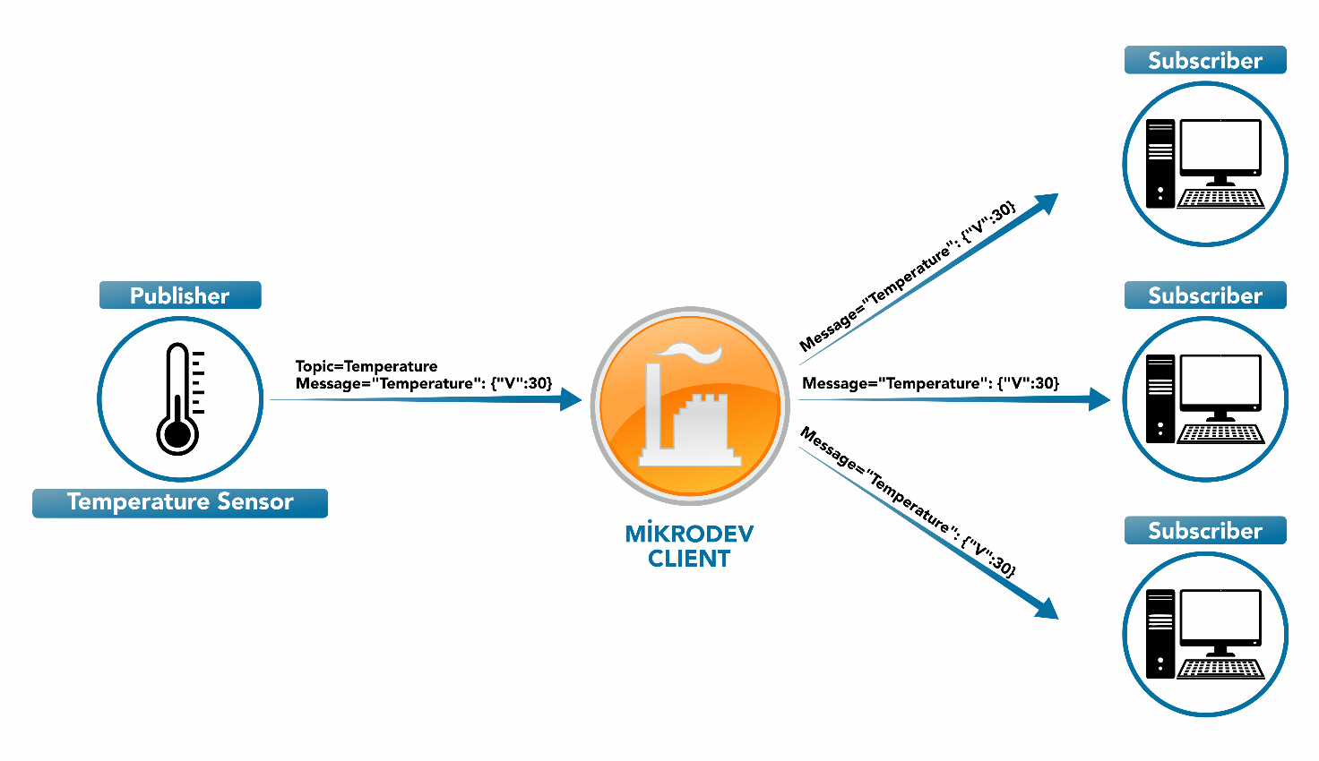
Payload structures that transmitted to subscriber units by Mikrodev Client are as below.
Example 1:
{
    "": {
          "LampCommand": {"V": 1}
    }
}
Example 2:
{
    "434523": {
                "PanelCommand": {"V": 0}
    }
}
In the payload structure in Example 1, Because of Device ID is not defined, it is specified as "0". "LampCommand": "1" information was sent to the device with {"V": 1} payload structure.
The payload structure in Example 2 has been published with the identity information of the device.
Component Text Content
Label and channel parameter texts can be written on some components and functions. The following functions are defined on the component that provides to dis-play text information on screen.
:CHNAME: shows the name of the channel where tag is located.
:CHDESC: shows the "Identification" information on the channel where the tag is located.
:CHSTATION: shows the “Station” information on the channel where the tag is located.
:CHSERVERIP: shows the “Server IP” information on the channel where the tag is located.
:TAGNAME: shows the “TagName” information.
:TAGDESC: shows the “Description” information of tag.
:TAGLOCATION: shows the “Location” information of tag.
:TAGDESC function provides to display tag definition information on the component with the following method.
A text value is entered in the "Description" parameter of the tag.
The "Run Function" parameter is defined in the relevant object for the dy-namic page which is needed restricted access. The "data1 = data2" information changes the tag names starting with data 1 in the directed page to the tag named data2. The information used after the semicolon indicates the access numbers for the page to be redirected.
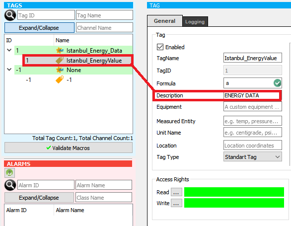
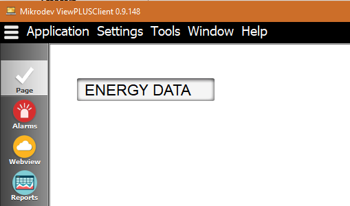
In order to display the description text,:TAGDESC function is written into the "Text Content" in the component "Object Properties".
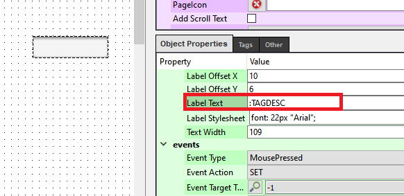
The created label is defined in the "Label Text" section under the "Tags" menu of the component.
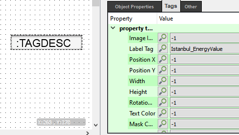
According to the defined operations of :TAGDESC function, the "Descrip-tion" parameter of the label data appears on the component.
Dynamic Page
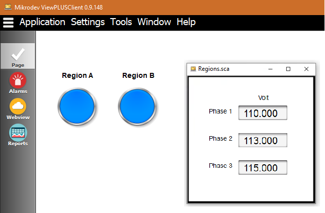
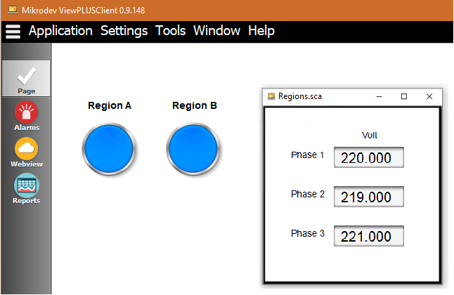
Instead of preparing multiple pages in the same format, we can create a reference page and show different tags on a single page.
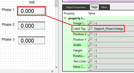
In the picture below, the references of the labels divided into two channels and to be interchanged can be listed as Phase1Voltage, Phase2Voltage, Phase3Voltage.
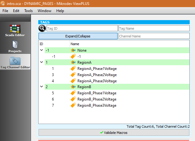
Reference tags are assigned to the components within the reference page.
In the “Run Function” parameter, the “RegionA = RegionB” information replaces the tag names that start with “RegionA” in the redirected page, with the names of the tags that start with “RegionB”.
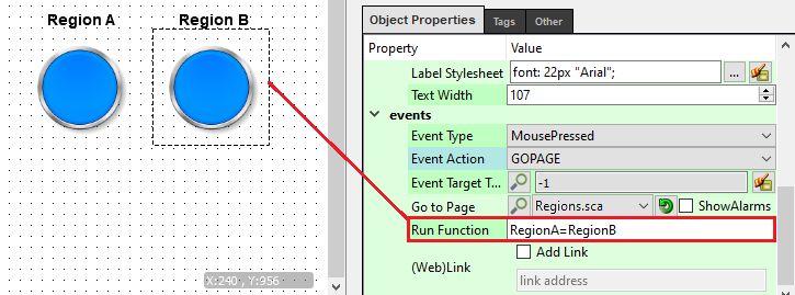
When the Region A button is clicked, the pop-up page named Region is opened and the reference tag information defined on the components appears.
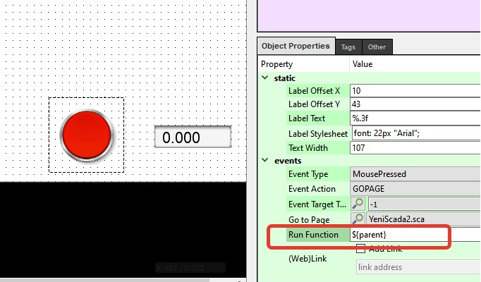
"$ {Parent}" function should be written into the "Run Function" parameter on the components that used in redirecting to different pages from the ref-erence page in order to maintain the dynamic structure when redirecting to different pages from the dynamic page.
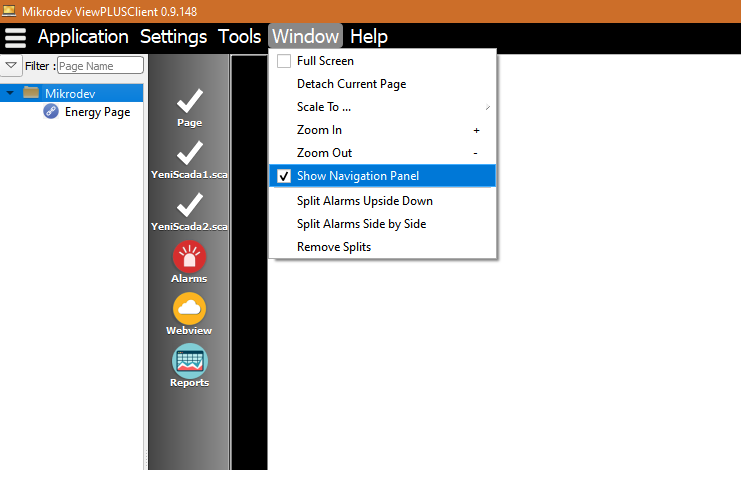
Navigation Panel
Created pages within the SCADA project can be displayed on the naviga-tion panel as pages or in folders.
The area that is marked in red, shows the navigation panel. The panel size can be increased or decreased from the right side of the navigation panel.

In order to perform operations on the navigation panel, right click with the mouse and select the operation to be performed in the displayed window.
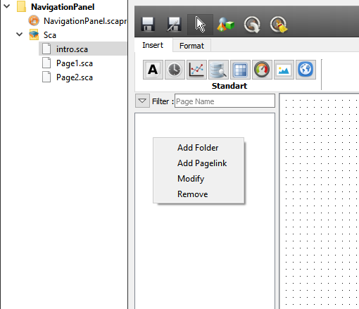
To create a folder on the navigation panel, "Add Folder" is marked and the folder name is written on the screen that appears.
In order to perform operations on the created folder, right click on the se-lected folder and select the desired action.
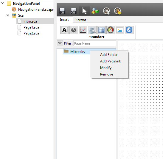
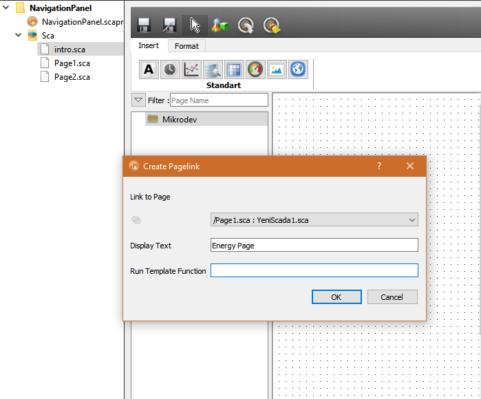
To move SCADA pages into the folder, right click on the folder and select “Add Pagelink”. The page to be added is selected in the appeared window.
The name of the page can be defined with the "Display Text" parameter and the dynamic structure can be used with the "Run Template Function" parameter.
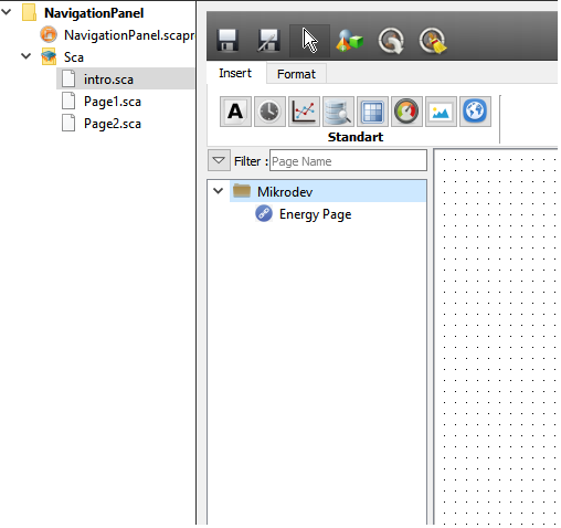
In figure 5, you can see The "Page1.sca" page which is added to the folder in the navigation panel.
Navigation panel can be opened or closed within the window tab on the Client screen.
Server Software
Server software must be associated with a project in order to run. When run from the editor menu, the currently open project is used by the server. To run the server independently of the editor, a folder is specified by selecting "Editor > Tools > Create Server Files" and the server files are copied to this folder. The "ServerEngine" widget is used to start the server. By default, the "ServerEngine" widget searches for a folder named "Project" in the same folder as itself.
The “Project” folder contains special files created by the editor. The main ones are; “MikrodevScada.ini” is “Project.zip”, “project pages with .sca extension” and component files. The server reads the information such as which database to connect to and where to keep the records in the “MikrodevScada.ini” file.
When the SCADA server is started for the first time, the user may be prompted to enter database connection information. The server can also open a project in a different folder using the following command line parameters.
“ServerEngine –dir “C:\Users\yg\Desktop\server\projectname“ ” -dir : Proje klasörü
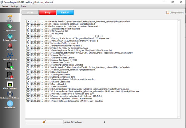
On the main screen of the server, there is a console where general system logs can be viewed. Important changes related to the server are shown on this console. More detailed server logs are saved in a separate file. When the “Start” button is pressed, the server establishes a connection with the field devices. After the connection is established, the server opens a port that clients can connect to and waits for incoming connections. When the server starts reading data from the field, it saves this data by sending it to the database server as specified in the project settings. Instant values of the data read from the field can be monitored on the label monitoring screen.
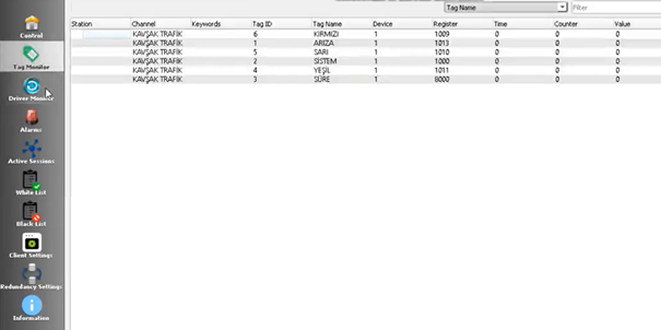
Filtering can be made on the instant values on the tag monitoring screen according to parameters such as tagId, tag name, channel name, device address. If there is a text in the form of "dced" next to the numerical data displayed in the "Value" field, this indicates that there is a connection problem between the device and the SCADA server. Information about device connection problems can be obtained from this console. The alarm screen, on the other hand, provides the history of the alarms that have occurred in the system and the current alarms to be observed.
Autostart The Server
Windows Platform
To start the server automatically, follow these steps (for a sample project called "TestProject"): • Create a shortcut to the desktop for the "ServerEngine.exe" program in the installation folder of ViewPLUS.
Creating a Shortcut • Right click on the created shortcut and select "Properties". • Change the "Target" field as follows (Change the file path according to your system):
"C:\Program Files (x86)\ViewPLUS\bin\ServerEngine.exe" -dir "C:\Users\username\TestProjesi" -start
• Then this shortcut "C:\Users\username\AppData\Roaming\Microsoft\Windows\Start Menu\Programs\Startup" copy below. Now the server will start automatically when the user logs in to the system.
• OperatorClient shortcut "C:\Users\username\AppData\Roaming\Microsoft\Windows\Start Menu\Programs\Startup" It can be automatically started at boot by copying it below.
Creating a Server Runtime
You can run the developed SCADA project on a different computer without installing ViewPLUS. For this, by selecting "Create Server Files" from the "Tools" menu, you can collect the necessary files for the project and server to work in a folder. By moving this folder, it is possible to run your project on different server machines.
For detailed information: Autostart The Server.
Client Software
Client Software; It allows end users to monitor and control the prepared project by connecting to the SCADA server over the internet or intranet.
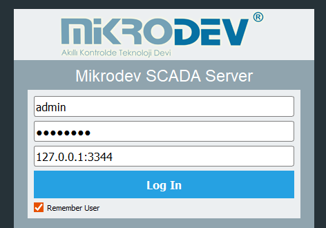
In order to connect to the SCADA server, you need to enter the user, password, server address and port information into the client software. You have to use the "User Manager" to create a new user. When this information is entered correctly, an encrypted connection is created between the server and the client software and the project entry screen sent from the server is displayed on the client.
In the "page selector" on the left side of the client screen, shortcuts for pages defined as "SCADA Tab" in the editor are displayed. The appearance and order of the shortcuts shown here can be adjusted in the editor. Besides these shortcuts, there are alarm panel and web view panel shortcuts.
Content displayed on the client; may vary depending on the access rights of the user, pages and defined tags. Pages that the user does not have access to are not shown in the "page selector" or the links to these pages will not work. If a visual element on the page contains a tag that the user does not have access to, the user is prevented from watching or controlling this element.
Create New User
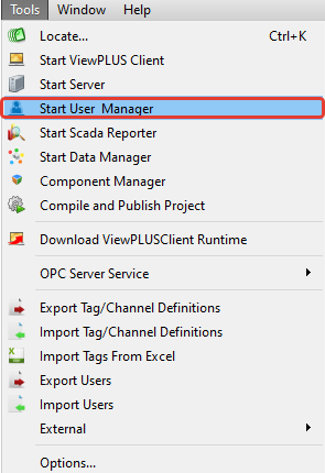
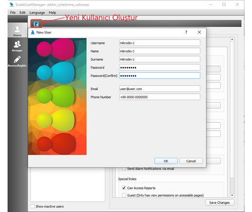
In order to create a user and make the necessary configurations in ViewPLUS, Start User Manager is selected under the Tools tab.

The New User tab is clicked and a new user is created by filling in the parameters on the page that opens. The created user is displayed under the username under the Users tab.
User Access Rights
User access privileges may vary depending on the user. Pages that the user does not have access to are not shown in the "page selector" or the links to these pages will not work. If a visual element on the page contains a tag that the user does not have access to, the user is prevented from watching or controlling this element.
Access Rights;
Read: These are the rights that users must have in order to see the tag values. Users who do not have the rights specified here will not be able to read this tag value.
Write: This is the right that users must have to change the tag values. Users who do not have the rights specified here cannot change this tag value.
For detailed information: User Definitions and Page Authorizations.
Reporting Software
You can use the Reporter to see and analyze the trend data logged by the SCADA software. The reporter allows you to report on three basic log data. These are tag logs, alarm logs and event logs.
Creating A Reporting Command
It is possible to generate report output in the desired format by calling the created filters via the reporter command line. For this, it is sufficient to give the necessary command line parameters to the reporting application. By using this feature, it is possible to generate automatic reports at certain time intervals via the "Task Scheduler" of the Windows operating system.
ScadaReporter.exe -database modpollread -user postgres -password laqhd -server localhost -port 5432 -query twohours -format csv -output "C:\Users\yg\Documents\Reports\Son2saat"
-database Name of the project database (same as the project) -user Database Username -password Database Username Password -server Database IP Address -port Database Connection Port -tnsname tns name for Oracle Databases -format Report output Format. Possible values: html,csv,xlsx,xml -query The name of the filter saved in the reporter. This parameter is required for the reporting command. If not, a report cannot be produced; The reporter interface opens. -output Path and name of the file to output
For detailed information: Reporter Screen.
Component Manager
To add new visual components and animations, you need to create "comx" component files. You can use the "Component Manager" for this.
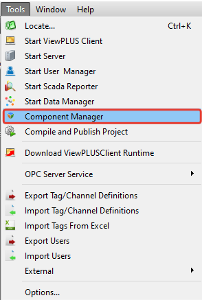
When ViewPLUS is started from the Tools menu, the components in the component folder of the relevant project are displayed.
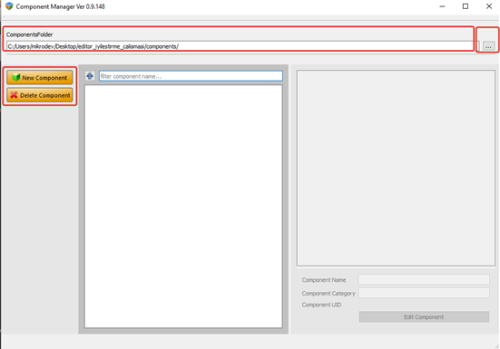
To add a New Component, select the image or images to be added by selecting "Add New Component". Images can be in (.png,.jpeg,.gif,.svg) formats.
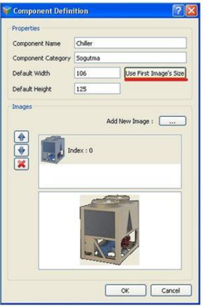
Component Name = Enter the name of the component.
Componet Category = The category name we want the component to be is written. If more than one component is desired to be under the same category, the same operations are repeated, the important thing is that the category name is the same, otherwise the component is added to a different category.
Use First image's size = This command is used to set the added object to its original size. While adding the objects that we want to change according to the data, it resizes the others according to the dimensions of the first picture.
For detailed information: Add New Component.
Advanced Settings
log_server.txt:
On Windows systems it is located in the following folder:
"C:\Users\username\AppData\Roaming\Mikrodev\ScadaServer\proje adı"
It is the file containing the detailed logs of the server.
log_serverstarter.txt :
It is the file containing the logs of the server monitor software.
OperatorClient.ini :
ServerEngine.ini:
On Windows systems it is located in the following folder:
"C:\Users\username\AppData\Mikrodev\ScadaServer\proje adı"
[Login]> ServerAdr: Database Address [Login]> DbName: Database Name [Login]> DbUserName: Database Username [Login]> DbPassword: Database Password [Connection] > Port: The default server port is 560. A different port can be selected by changing this parameter. [Logging] > IsLogging:Data logging can be enabled/disabled(true/false) [Logging] > IsLoggingDısconnections: It can be selected whether to log disconnections or not. [REDUNDANCY]> ServerMode: It determines the redundant operation mode. This value can be PRIMARY or BACKUP. When this mode is set to backup, the server communicates with the PRIMARY server and creates a redundant file. [REDUNDANCY]> PrimaryIP: The PRIMARY server IP address to which the server in BACKUP mode will connect is written in this field. [REDUNDANCY]> PrimaryPORT:The port number of the PRIMARY server to which the server in BACKUP mode will connect is written in this field. [REDUNDANCY]> Timeout: It is the value in seconds that determines how long the BACKUP server will be active after the PRIMARY server is inactive.
To get more information: