ViewPLUS SCADA Alarm Screens Application Notes
ViewPLUS Client Screen Alarm Page
The ViewPLUS Client screen alarm page consists of two parts.
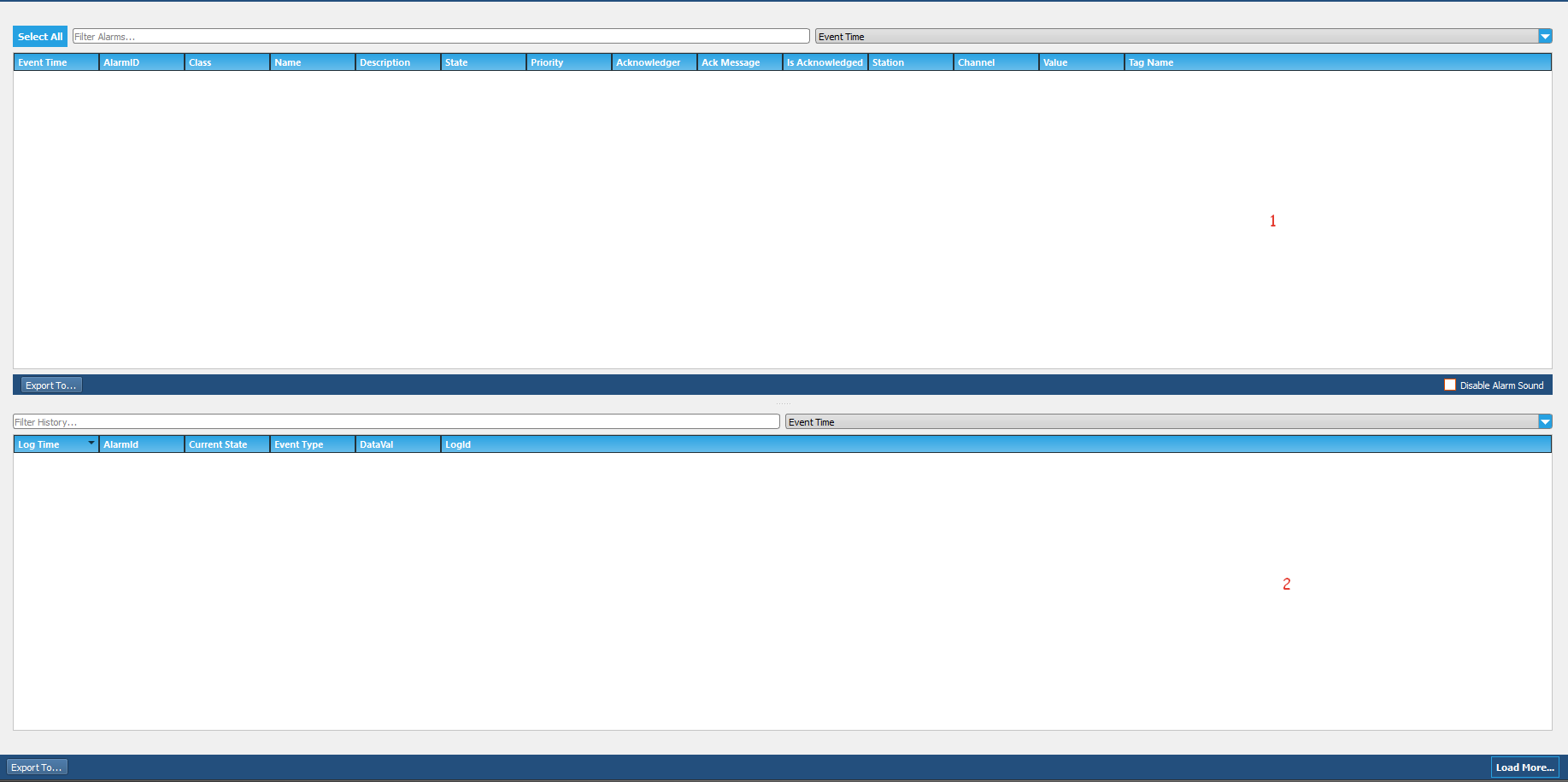
The active alarm section, where active alarms are monitored, is indicated by number 1, while the alarm log section, which contains past alarms, is indicated by number 2.
Note: The information in this document is valid for ViewPLUS version 0.9.154 and later.
The alarms on the client screen can play in three different alarm sounds based on their priority level. To view the range of priority level values, open the Alarms section in the ViewPLUS channel tag editor. Select any alarm in the Alarms section and hover the mouse over the priority field to see that the information screen opens.
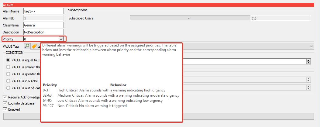
The priority levels for high-level alarms range from 0 to 31,
For medium-level alarms range from 32 to 63,
For low-level alarms range from 64 to 95,
For warning alarms specifically added, the priority level ranges from 96 to 127.
What sets warning alarms apart from other alarms is that when an alarm condition occurs, they do not play an alarm sound. Instead, they operate as silent alarms.
Note: If all alarm sounds are to be turned off, the "Mute Alarm Sounds" option on the client screen should be checked.
Active Alarms Section
The features in the active alarm section of the client screen are indicated by numbering them in Figure 2.
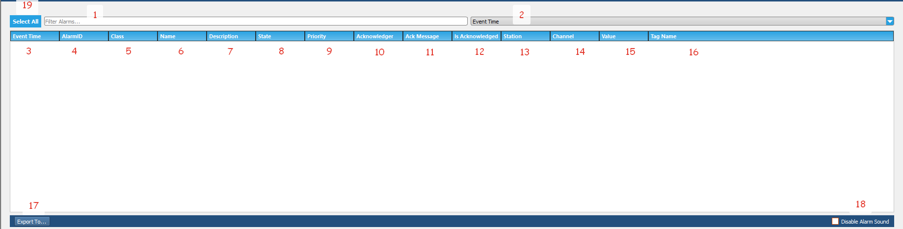
Number 1 Filter Alarms: If an alarm filter is to be used, the expression to be filtered in this section is entered.
Number 2: If an alarm filter is to be used, the feature to be filtered is selected from this section. The columns displayed on the screen are presented as filtering options here.
Number 3 Event Time: The time of occurrence of the alarm or the time when the last value of the alarm tag received by the SCADA system is written in this column if the alarm is idle.
Number 4 AlarmID: The alarm ID information in the ViewPLUS SCADA Editor -> Tag Channel Editor -> Alarms section of the created alarm is written in this column. A different alarm ID is automatically assigned to each alarm by the ViewPLUS SCADA editor during alarm creation.
Number 5 Class: The name of the class in the ViewPLUS SCADA Editor -> Tag Channel Editor -> Alarms section to which the created alarm is associated is written in this column.
Number 6 Name: The name of the alarm in the ViewPLUS SCADA Editor -> Tag Channel Editor -> Alarms section to which the created alarm is associated is written in this column.
Number 7 Description: The description of the created alarm in the ViewPLUS SCADA Editor -> Tag Channel Editor -> Alarms section to which the alarm is associated is written in this column.
Number 8 State: The current status of the created alarm is written in this column. There are two different states for created alarms, [TRG] Alarm triggered and [IDL] Alarm idle.
For example, when an alarm value is sent to the tag associated with the alarm, the alarm state of the created alarm will be [TRG] alarm triggered.
If the created alarm is not acknowledged and a value different from the alarm value is sent to the tag associated with the alarm, the alarm state will be [IDL] alarm idle. In this case, it is evaluated by ViewPLUS SCADA as if the alarm is still active. If the alarm is to be removed from the active alarms section, it must be acknowledged.
If the created alarm is acknowledged and a value different from the alarm value is sent to the tag associated with the alarm, the alarm will be removed from the active alarms section.
Number 9 Priority: The priority of the generated alarm is written in this column in the ViewPLUS SCADA Editor -> Tag Channel Editor -> Alarms section. By applying an alarm filter based on the priority value entered here, you can list your alarms in order of priority. 255 different levels can be defined as alarm priority.
Number 10 Acknowledger: If the generated alarm has been acknowledged, the username of the person who acknowledged it is written in this column.
Number 11 Ack Message: If the generated alarm has been acknowledged, the acknowledgement message is written in this column.
Number 12 Is Acknowledged: If the generated alarm has been acknowledged, the acknowledgement status ([ACK] acknowledged) is written in this column.
Number 13 Station: The station information of the tag associated with the generated alarm is written in this column in the ViewPLUS SCADA Editor -> Tag Channel Editor -> Tag Channel.
Number 14 Channel: The name of the tag channel where the generated alarm is associated is written in this column in the ViewPLUS SCADA Editor -> Tag Channel Editor.
Number 15 Value: The current value of the tag associated with the generated alarm is written in this column.
Number 16 Tag Name: The name of the tag associated with the generated alarm is written in this column in the ViewPLUS SCADA Editor -> Tag Channel Editor -> Alarms section.
Number 17 Export To: The generated alarms can be exported from this section. The format of the exported file can be Excel, CSV, HTML, or XML.
Number 18 Disable Alarm Sound: The alarm sounds of the generated alarms can be turned on or off from this section.
Number 19 Select All: All of the alarms that occur can be selected from this section. Thanks to this feature, alarms can be confirmed collectively.
Alarm Logs Section
The properties in the alarm log section of the client screen are indicated by numbering in Figure 3.
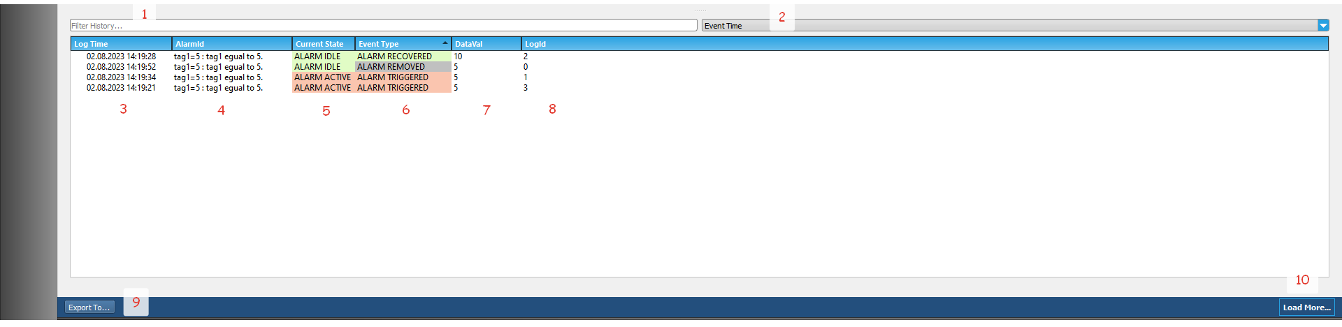
Number 1 Filter Alarms: If an alarm filter will be used, the expression to be filtered is entered in this section.
Number 2: If an alarm filter will be used, the feature to be filtered is selected from this section. The columns on the screen are presented as filtering options.
Number 3 Log Time: The creation time of the generated alarm or the reading time of the tag value by SCADA, if the alarm is idle, is written in this column of the alarm tag.
Number 4 Alarm ID: If the generated alarm is added with the alarm name in ViewPLUS SCADA Editor -> Tag Channel Editor -> Alarms section, its definition is written in this column.
Number 5 Current State: The current status of the generated alarm is written in this column. Two different states occur for generated alarms: alarm active or alarm idle.
For example, when the alarm value associated with the tag is received, the alarm state will be alarm active. If a value different from the alarm value associated with the alarm tag is received without acknowledging the generated alarm, the alarm state will be idle.
Number 6 Event Type: The event types of the generated alarms are written in this column. The possible event types are as follows:
- Alarm Triggered: If the alarm value is received for the tag associated with the alarm, it will be written as alarm triggered in this column.
- Alarm Removed: If the generated alarm is acknowledged (acknowledged), and a value different from the alarm value associated with the tag is received, it will be written as alarm removed in this column.
- Alarm Acknowledged: If the generated alarm is acknowledged, it will be written as alarm acknowledged in this column.
- Alarm Recovered: If the generated alarm is not acknowledged, and a value different from the alarm value associated with the tag is received, it will be written as alarm recovered in this column.
Number 7 Data Val: The current value of the tag associated with the generated alarm is written in this column.
Number 8 Log ID: The log IDs of the generated alarm stored in the database are written in this column.
Number 9 Export to: Generated alarms can be exported from this section. The format of the exported file can be in Excel, CSV, HTML or XML.
Number 10 Load More: Previously saved alarms in the database that do not appear in the alarm log can be brought to the alarm log section with this option.
Server Engine Screen Alarm Page
The alarms created via the SCADA editor can be monitored not only from the client screen but also from the server screen. The server screen alarm page consists of three tabs.
Active Alarms Section
To monitor active alarms from the server screen, go to ViewPLUS SCADA Editor -> Tools -> Start Server -> Alarms -> Active Alarms tab. The active alarms tab on the server screen has the following features, numbered in Figure 4.
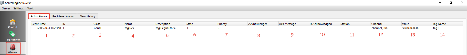
Note: The features in the active alarm section of the client screen and the active alarm tab of the server screen are similar to each other. If the accuracy of the alarms created on the client screen needs to be verified, these two sections can be compared.
Number 1 Event Time: The time of occurrence of the alarm or if the alarm is idle (not active), the time of the last reading of the value of the associated tag by SCADA is written in this column.
Number 2 AlarmID: The ID of the alarm that is listed in ViewPLUS SCADA Editor -> Tag Channel Editor -> Alarms section is written in this column. Each alarm is assigned a different ID automatically by ViewPLUS SCADA Editor when it is created.
Number 3 Class: The name of the class that is listed in ViewPLUS SCADA Editor -> Tag Channel Editor -> Alarms section is written in this column.
Number 4 Name: The name of the alarm that is listed in ViewPLUS SCADA Editor -> Tag Channel Editor -> Alarms section is written in this column.
Number 5 Description: The description of the alarm that is listed in ViewPLUS SCADA Editor -> Tag Channel Editor -> Alarms section is written in this column.
Number 6 State: The current state of the alarm is written in this column. When the value of the associated tag becomes an alarm value, the value in this column becomes 1.
If a value other than the alarm value is received for the associated tag and the alarm is not acknowledged on the client screen, the value in this column will be 0.
If the alarm is acknowledged on the client screen and a value other than the alarm value is received for the associated tag, the alarm is not considered an active alarm and will be removed from the active alarm screen.
Number 7 Priority: The priority of the alarm that is listed in ViewPLUS SCADA Editor -> Tag Channel Editor -> Alarms section is written in this column. You can filter alarms based on priority level and list them in order of priority. There are 255 different priority levels that can be defined for alarms.
Number 8 Acknowledger: If the alarm is acknowledged on the client screen, the username of the user who acknowledged it is written in this column.
Number 9 Ack Message: If the alarm is acknowledged on the client screen, the acknowledgement message is written in this column.
Number 10 Is Acknowledged: If the alarm is acknowledged on the client screen, the acknowledgement status is written in this column. It will show "acknowledged" for acknowledged alarms.
Number 11 Station: The station information of the tag associated with the alarm, which is listed in ViewPLUS SCADA Editor -> Tag Channel Editor -> Tag Channel, is written in this column.
Number 12 Channel: The name of the tag channel associated with the alarm, which is listed in ViewPLUS SCADA Editor -> Tag Channel Editor -> Tag Channel, is written in this column.
Number 13 Value: The current value of the tag associated with the alarm is written in this column.
Number 14 Tag Name: The name of the tag associated with the alarm, which is listed in ViewPLUS SCADA Editor -> Tag Channel Editor -> Alarms section, is written in this column.
Registered Alarms Section
To view all alarms created from the editor on the server screen, go to ViewPLUS SCADA Editor -> Tools -> Start Server -> Alarms -> Registered Alarms tab. The properties in the server screen registered alarms tab are numbered and indicated in Figure 5.
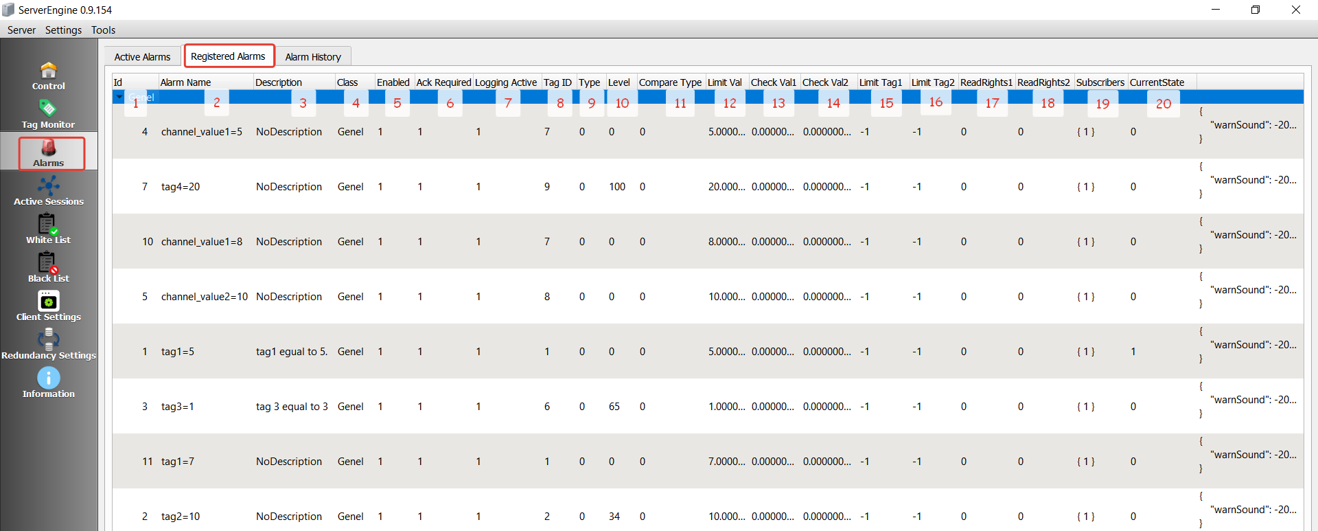
Number 1 ID: The ID of the created alarm is written in this column in the ViewPLUS SCADA Editor -> Tag Channel Editor -> Alarms section.
Number 2 Alarm Name: The name of the created alarm is written in this column in the ViewPLUS SCADA Editor -> Tag Channel Editor -> Alarms section.
Number 3 Description: The description of the created alarm is written in this column in the ViewPLUS SCADA Editor -> Tag Channel Editor -> Alarms section.
Number 4 Class: The class name of the created alarm is written in this column in the ViewPLUS SCADA Editor -> Tag Channel Editor -> Alarms section.
Number 5 Enabled: Whether the checkbox for "Enabled" in the ViewPLUS SCADA Editor -> Tag Channel Editor -> Alarms section is checked or not is indicated in this column. If the checkbox is checked when creating the alarm, the value written here will be 1, and if it is not checked, the value written here will be 0. This option allows the created alarm to be enabled or disabled.
Number 6 Ack Required: Whether the checkbox for "Ack Required" in the ViewPLUS SCADA Editor -> Tag Channel Editor -> Alarms section is checked or not is indicated in this column. If the checkbox is checked when creating the alarm, the value written here will be 1, and if it is not checked, the value written here will be 0. This option determines whether the created alarm will require user acknowledgment (acknowledge).
Number 7 Logging Active: This column indicates whether the "Log into database" checkbox is checked or unchecked while creating the alarm in ViewPLUS SCADA Editor -> Tag Channel Editor -> Alarms section. If the checkbox is checked during alarm creation, the value in this column will be 1, otherwise it will be 0. This option is used to decide whether to record the alarm in the database or not.
Number 8 Tag ID: This column shows the associated tag ID in the ViewPLUS SCADA Editor -> Tag Channel Editor -> Alarms section for the generated alarm.
Number 9 Type: This section is reserved for future developments. (No function has been defined yet.)
Number 10 Level: This column shows the priority of the alarm created in ViewPLUS SCADA Editor -> Tag Channel Editor -> Alarms section.
Number 11 Compare Type: This column shows the condition type of the created alarm.
If the condition is set to "Equal to limit ", the value in this column will be 0.
If the condition is set to "Smaller than limit ", the value in this column will be 2.
If the condition is set to "Greater than limit", the value in this column will be 1.
If the condition is set to "In range ", the value in this column will be 3.
If the condition is set to "Out of range", the value in this column will be 4.
Number 12 Limit Val: This column shows the limit value of the created alarm. If a specific range value is specified for the alarm to occur, the value in this column will not be taken into account.
Number 13 Check Val 1: This column shows the minimum range value entered for the created alarm. If a specific limit value is specified for the alarm to occur, the value in this column will not be taken into account.
Number 14 Check Val2: This column shows the maximum range value entered for the created alarm. If a specific limit value is specified for the alarm to occur, the value in this column will not be taken into account.
Number 15 Limit Tag1: This column shows the associated tag ID in the ViewPLUS SCADA Editor -> Tag Channel Editor -> Alarms section for the generated alarm.
Number 16 Limit Tag2: This section is reserved for future developments. (No function has been defined yet.)
Number 17 ReadRights1: This section is reserved for future developments. (No function has been defined yet.)
Number 18 ReadRight2: This section is reserved for future developments. (No function has been defined yet.)
Number 19 Subscribers: This column shows the subscriber user ID in the ViewPLUS SCADA Editor -> Tag Channel Editor -> Alarms section for the generated alarm. Subscribing users must be defined for the created alarms to be monitored from the client screen.
Number 20 CurrentState: This column indicates the current state of the alarm. When the associated tag receives an alarm value, the value in this column will be 1. If a value outside of the alarm threshold is received, the value in this column will be 0.
Alarm History Section
To view all alarms created through the editor from the server screen, open ViewPLUS SCADA Editor -> Tools -> Start Server -> Alarms -> Alarm History tab. The features in the server screen alarm history tab are numbered and indicated in Figure 6.
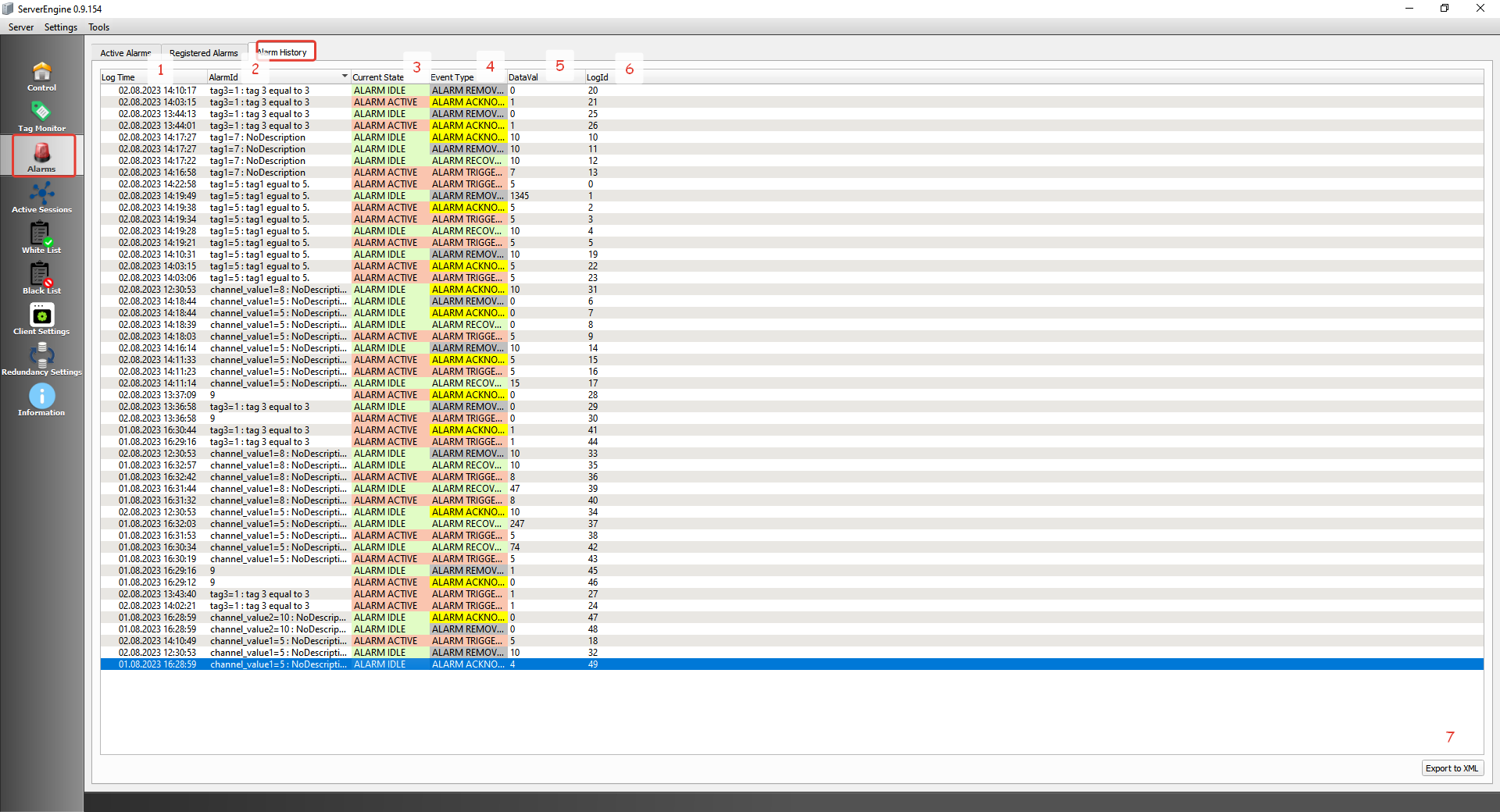
Note: The properties in the Client screen's alarm log section and the properties in the Server screen's alarm history tab are similar in structure. If the accuracy of the alarms created on the Client screen needs to be verified, these two sections can be compared.
Number 1 Log Time: The time when the alarm was created or, if the alarm is idle, the time when the latest value of the alarm tag was read by SCADA is written in this column.
Number 2 Alarm ID: If the alarm is added along with its name in the ViewPLUS SCADA Editor -> Tag Channel Editor -> Alarms section, its definition is written in this column.
Number 3 Current State: The current state of the alarm is written in this column. Two different states occur for created alarms: alarm active or alarm idle. For example, when the value of the tag associated with the alarm arrives, the alarm state of the created alarm will be alarm active. If the alarm is not acknowledged and a value different from the alarm value arrives at the tag associated with the alarm, the alarm state will be alarm idle.
Number 4 Event Type: The event types of the generated alarms are written in this column.
The possible event types are as follows:
- Alarm Triggered: If an alarm value is received for the tag associated with the alarm, "alarm triggered" will be displayed in this column.
- Alarm Removed: If the alarm is acknowledged and a different value than the alarm value is received for the tag associated with the alarm, "alarm removed" will be displayed in this column.
- Alarm Acknowledged: If the alarm is acknowledged, "alarm acknowledged" will be displayed in this column.
- Alarm Recovered: If the alarm is not acknowledged and a different value than the alarm value is received for the tag associated with the alarm, "alarm recovered" will be displayed in this column.
Number 5 DataVal: The current value of the tag associated with the generated alarm is displayed in this column.
Number 6 LogId: The log IDs of the generated alarms that are saved in the database are displayed in this column.
Number 7 Export to XML:** The generated alarms can be exported from this section. The format of the exported file can be XML.