MODBUS Application Notes
MODBUS COMMUNICATION
Modbus can provide communication between approximately 247 devices. The operating logic is based on data exchange between a master device and one or more devices connected to the master on the same network. It is often used to interconnect a controller computer with remote terminals. Data transfer is provided in the form of ones and zeros, that is, in bits. Although there are many versions, the most used versions are Modbus RTU and Modbus TCP/IP.
This guide shows how Modbus TCP/IP and Modbus RTU communications are implemented on Mikrodev products.
If our device is Mikrodev - PLC product, you can program it on Mikrodiagram program. If our device is Mikrodev RTU product, we use Telediagram program. So our programmers are customized to our products. The blocks used and their settings are the same in Telediagram and Microdiagram programs. In our devices, under the function blocks, 2 separate addressing as Block address (B:) and Modbus address (M:) are used. B: is used for functions belonging to our product family, and M: is used for Modbus communication.
MODBUS TCP/IP Communication
As we mentioned before, there can be 1 Master/Master and up to 246 Slave/Slave devices in MODBUS Communication. We use TSB block for our Master or Slave device to communicate with TCP/IP protocol. We can add function blocks from the Door Types window or by right-clicking in the project area.

As you can see in Figure 1, we can set the IP and Port information from inside the TSB block, as well as from the outside using a register. To observe the connection status, we can put a flag or register on the Con output to observe its value. 0 means no connection, 1 means there is a connection. In function block settings, it is more practical to write non-variable values in the block. You can see the TSB block settings in Figure 2.


If our device is going to be Modbus Master by connecting our TSB Block to a Master block, we select the TCP client option from the Parameters;TCP Socket section (Figure 2) and enter the Server Port and Server IP of the Slave device to which we want to connect.;If our device is going to be Modbus Slave in communication by connecting our TSB Block to a Slave block, Parameters;TCP Socket setting (Figure 2) TCP Server is selected. TCP Server settings section will be active. Here, the TCP/IP port of our slave device is written. If we want, we can limit the devices to be connected to our device using the IP filter method by filling in the Server IP section. Supported and desired media type (Figure 3) can be selected from Ethernet, GSM or WiFi.
MODBUS TCP/IP Slave Settings
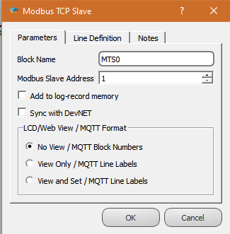
We explained TSB settings in the previous section. Here, TCP Socket, TCP Server should be selected in TSB block for Slave device setting and Port number should be entered. For MODBUS communication, we add MODBUS TCP Slave, MTS block to TSB Block (Figure 4).

The block connections for the slave settings of our device are shown in Figure 4. We define the slave ID identifier from inside the MTS function block (Figure 5). We can also observe the data traffic of the Slave side in Modbus Communication. For this, if we want to get the number of packets received, the number of faulty packets and the last packet status information, we can use it by connecting a flag or register to the Rx, Err, Sta outputs, respectively.
MODBUS TCP/IP Master Settings
After making the relevant settings from the TSB settings (MODBUS TCP/IP Communication), we add the MODBUS TCP Master, MTM block to our TSB Block (Figure 6). If it is in the function block, you can see the Request Timeout and other settings.

We can send requests from our master device to Slave devices. These requests can be made by reading the values of the registers/registers defined by the MODBUS addresses (M:) in Slave devices or writing values to these registers. When a rising edge hits the trigger pin of the read/write blocks, the reader/writer command is sent to the Slave device and a response is expected. We can add MODBUS Reader or Printer blocks to our MTM block as shown in Figure 7. These blocks are shown as Word, Float and Long. MWR/MWWr, Word Reader/PRINTER 16-bit positive it is used for integer values. MFR/MFWR, Float Reader/Printer is used for 32-bit decimal values. MLO/MLWR is used for Long Readers/printers and 32-bit integers.
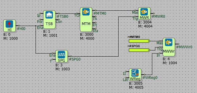
Instead of reading and writing values from consecutive registers of the same data type in separate blocks, we can read and write tables with a single function block. It is recommended to use MODBUS Read/Write Table for this. The MODBUS Status block is recommended to check the connection status of a particular Slave device. When a negative word value is to be read, the MWR block is connected to the Long transaction block, and the transaction type is selected as “Word to Signed” and the negative values are read.MODBUS reader and writer blocks settings are shown in Figure 8 and Figure 9.
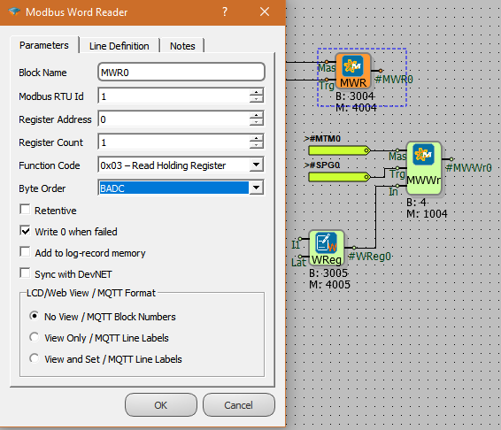
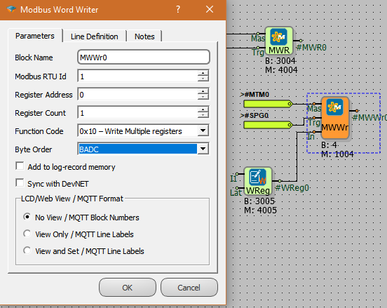
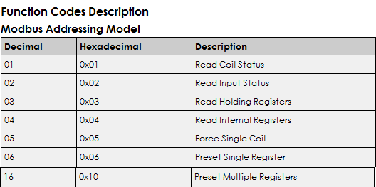
Common values from Figure 8 and 9 are ID number, Register Address and Byte Sequence of the Slave device to be read/written. Function Code varies for register type and value. You can also see Other Settings in the pictures.
Function Code values are 4 types according to the type of registers on the related Slave. Reading values are classified as follows.
Function Code values are divided into 3 for the Write operation on the corresponding Slave. The classification of write values is as follows.
Byte Order varies by manufacturer. The correct order can be found in the device user's manual.
If we want the values to be permanent or 0 value written when there is no connection, adding it to the log-kayıt memory, Dev-net synchronization or seeing it from the web interface, this section is in this section. We can make adjustments.
MODBUS RTU Communication
As TCP protocol is used in MODBUS TCP/IP communication. RS232 and RS485 serial port communication is used in MODBUS RTU communication. For the cable connections of RS232 and RS485 devices, refer to the product user manual.
Serial port communication is defined in our program as follows.
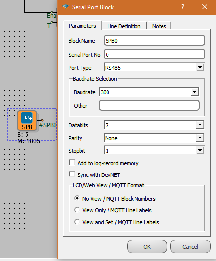
Its settings for serial port communication are shown in Figure 11. Serial Port No selection is to define which port of our device is connected to. Serial Port No:0 for RS485 is 1 for RS232.
Port type should be selected accordingly. Baudrate serial communication value can be selected from the list, or the Other option can be used for values that are not in the list. Databits, Parity and Stopbit data are also entered. In this way, Serial port settings are completed.
In this section, MODBUS RTU Slave and MODBUS RTU Master device settings will be displayed respectively.
MODBUS RTU Slave Settings
The physical cable connections and port settings of our MODBUS RTU supported Slave device are shown in the Serial Port Block in the previous section (MODBUS RTU Communication). In this section, we will show the MODBUS RTU Slave settings of my device. We select MODBUS RTU Slave from the Door Types section in programming and connect it to the Serial Port Block.
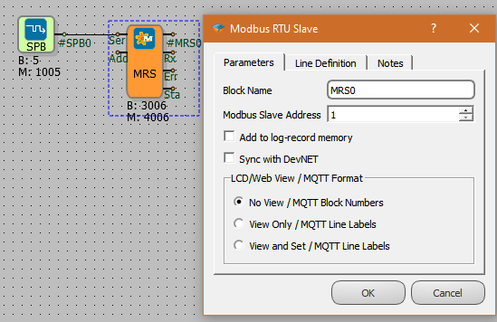
MRS; When MODBUS RTU Slave block is clicked, Modbus Slave Address definition section is displayed. In Picture 9, Modbus Slave Address is defined as 1. We can also define the Modbus Slave address of our slave device here. Using the Rx, Err, and Sta connections of the MODBUS RTU Slave block, we can see the received data packet count, the number of faulty packets and the status of the last packet data by connecting a flag or register.
MODBUS RTU MASTER Settings
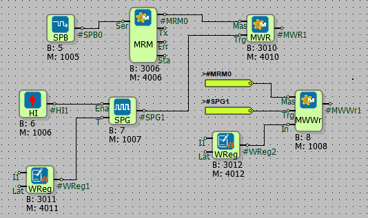
MODBUS RTU Slave, MODBUS RTU Master device is required to receive or send data from the device. For this, the settings of our device, which will be defined as MODBUS RTU Master, are explained in this section. In programming, MODBUS RTU Master , connection of MRM block is as shown below.
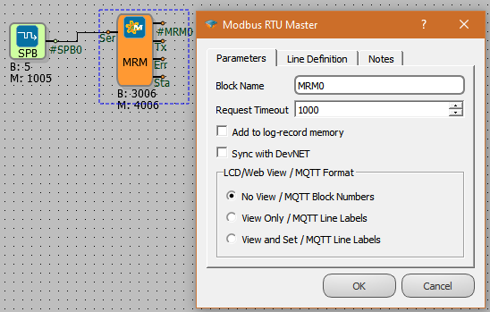
Request Timeout, which is the data waiting time, can be set from Function Block settings, block name/Line definition. By connecting a register or flag to the Tx, Err and Sta outputs of the function block, the number of data packets sent, the number of faulty packets and the last packet status can be seen. A suitable MODBUS Word, Long, Float reader or writer block can be connected to the MRM output to read or write data from Slave devices with MODBUS RTU protocol. Instead of reading and writing values from consecutive registers of the same data type in separate blocks, we can do table read-write with a single function block. For this, it is recommended to use the MODBUS Read/Write Table. MODBUS Status block is recommended to check the connection status of a particular Slave device.
MODBUS read and write blocks are also used in common with TCP and RTU.
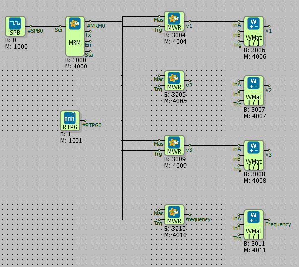
Sample Project: Read Analyzer with MODBUS RTU Protocol
In order to be able to read the analyzer with the MODBUS RTU protocol, the analyzer must support the RS232 and RS485 connections, which are the connection types in our device. In order to provide Serial Communication from supporting devices, we need to know the required values. You can find the information in the user manual of the device to be connected.
For example, we will read an analyzer with RS485 communication. For this, Port type RS485 and Port no:0 are selected. If we used RS232, Port type RS232 and Port no:1 should be selected. We enter the baudrate value of the analyzer from the Baudrate Selection section. If this value is not in the list, we can enter Other. When we enter the Veribits, parity and stop bit values for the connection and click OK, our Seriport block settings are completed.
We add Modbus RTU Master and Read write blocks. In read-write blocks, we use it to access values that do not have read or write protection from the analyzer. Modbus RTU Id, Register Address, Function Code and Byte Order settings should be entered in this block. These settings can be learned from the Analyzer user manual or from the interface on it, if available. Updating the values to be read/written occurs when a rising edge signal arrives at the Ttk pin on the Modbus Read/Write Blocks. It is recommended to use the Modbus Read/Write Table, as the values of the same type of registers with multiple sequential addresses are read in value readings.
Other Function Blocks and Features
Function blocks used and not mentioned with the MODBUS protocol are described in this section.
MODBUS Read/Write Table Block
It is used in MODBUS TCP or RTU Master blocks. It is recommended to use this function block when reading data values from registers of the same type with sequential addresses, to avoid duplication. The connection type is as shown below.
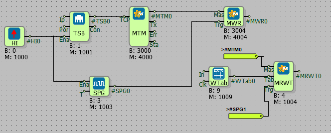
Table settings are the same as Read and write settings. The advantage of Modbus Read/Write Table is that we can read or write values to Sequential address registers with a single
MODBUS Status Function Block
Connects to MODBUS Master blocks. It is used when we want to get status information of slave devices. Connection type and settings are as shown below.
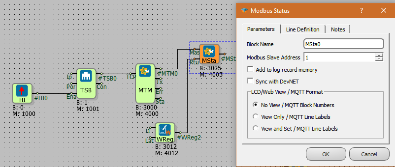
The MSta Mas entrance is the entrance to the Master block. Rtu is the Slave ID entry from which we want to receive status information. It can be defined by adding a register to this part or from the settings section.
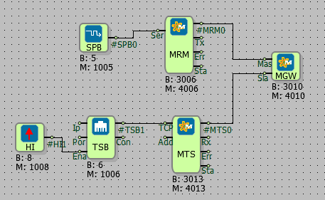
MODBUS Gateway Function Block
MODBUS Gateway devices are basically used to create a gateway for master units in MODBUS TCP network to access slave units in MODBUS RTU network. Request packets coming over MODBUS TCP are converted into MODBUS RTU packets and sent to the RTU network. It also receives the response from the RTU network and sends it to the MODBUS TCP network. On the MODBUS TCP side, the number of TRANSACTION in requests and responses must be the same, and it is also the duty of the GATEWAY device to provide this. Mikrodev Control devices can be programmed to work simultaneously as GATEWAY among the protocols they support. One of the blocks that provides this is the MODBUS GATEWAY block.
MODBUS GATEWAY block can serve in 2 directions listed below:
1- MODBUS TCP Master device to MODBUS RTU Slave device 2- MODBUS RTU Master device to MODBUS TCP Slave device
Master in block usage and Slave blocks are enough to start working as GATEWAY. In case of a request for a different ID than the Modbus ID on the slave block side, the relevant request will be read through the master block. Note that Modbus RTU Slave ID and Modbus TCP/IP Slave ID are not the same.