NTP Application Notes
Overview
NTP (Network Time Protocol) is a protocol used to synchronize the clocks of computers on packet-switched networks with variable latency.
NTP uses the User Datagram Protocol (UDP) over port 123.
NTP settings are made from either the /etc/ntp.conf or /etc/xntp.conf file, depending on which distribution is used.
Mikrodev, MP211 PLC and RTU device family support Network Time Protocol – NTP so our devices have real time values.
NTP Syncronise Block Definitions
Connections
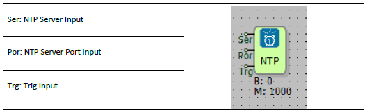
Ser: NTP Server Input
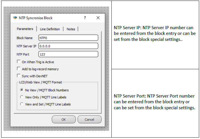
NTP Server IP can be defined from this entry in the block.
Por: NTP Server Port Input
NTP Server Port number can be defined from this entry in the block.
Trg: Trig Input
It is the trigger input for synchronization. It works as a rising edge.
Custom Settings
Note: In order for the trigger to work, the "On When Trig is Active” option must be selected from the block custom settings.
Block Explanation
Since the NTP Synchronization Block is active with the high edge signal coming to the Trg-Trigger pin, Real Time Pulse Generator, Symmetrical Pulse Generator or Binary Register block can be connected to the block trigger input. Blocks connected to the trigger input are used to set the match frequency with the NTP server.
For NTP server settings, NTP server IP is entered in the NTP Server IP section of the function block. In the NTP port part, the server port is entered. On When Trig is Active option, on the other hand, enables the block to run as a result of the trigger.
If desired, NTP Server IP and NTP Port information can also be defined by connecting to the Ser and Por pins of the NTP Syncronise Blocks.
Sample Application
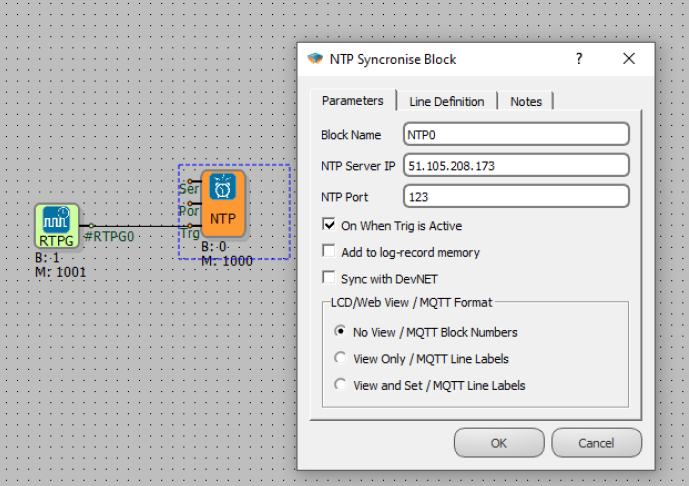
The timing frequency of the real-time pulse generator is 1 per second. The RTPG block sends a trigger once per second to the NTP synchronization block, performing a time synchronization with the NTP server once per second.