Mikrodiagram Editor
Introduction
About Mikrodiagram
Mikrodiagram is an editor software for used programming of Mikrodev PLC family devices that developed by Mikrodev. Mikrodiagram provide to you perform very complex projects quickly with a visual and easy-to-understand interface.
Mikrodiagram library keep advanced blocks that will facilitate complex aplications such as “PID, astronomical timer” as well as basic logic blocks like “AND, OR, XOR”.
Settings such as program installation and update, online monitoring and firmware update are presented in Mikrodiagram by connecting to devices via different interfaces(USB/TCP).
Setup
System Requirements
Minimum computer requirments for Mikrodiagram setup:
Operating system: Microsoft Windows XP/Vista/7/8/10/12 (32/64 Bit), Linux
CPU: 500 Mhz
RAM: 512 MB
Video Card: 128 MB
Disk Area: 200 MB
Mikrodiagram Setup
Mikrodiagram software is designed to work with current Windows versions. The installation file can be downloaded free of charge from the following internet address:
Mikrodiagram setup is completed by following the directions on the screen.
Usb Driver Setup
STM Processor USB driver installation file…………………… can download in internet adress.
USB driver setup is completed by following the directions on the screen.
= Note:= There is no need to install a USB driver when Mikrodiagram is installed on a computer with Windows 10 or higher operating system.
Interface
Menu Options
In Mikrodiagram menu options "File, Edit, Build, Tools, Window and Help" menus are available.
![]()
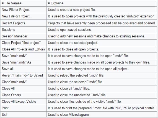
- File Menu
Basic program filing operations can be done from Mikrodiagram file menu.
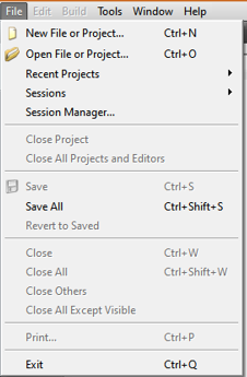
File menu options are described on the tablature.
- Edit Menu
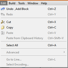
Edit menu is used for undoing the operation, restoring the undo operation, renaming, cutting, copying, pasting, and selecting all operations.
- Build Menu
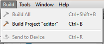
The Build menu is used for compiling the project.
- Tools Menu
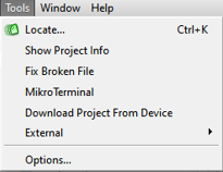
From the Tools menu, you can access Mikrodiagram interface configuration settings and the "Mikroterminal" program where the USB serial port device settings are made.
- Window Menu
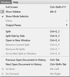
Window menu is used to Mikrodiagram make to design window settings. There are features such as full screen, sidebar display, mode selector display, screen splitting in various shapes
- Help Menu

From the help menu you can access Mikrodiagram "help text" and "about Mikrodiagram" options.
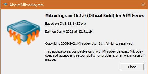
Information on Mikrodiagram software version can be found on the "About Mikrodiagram" tab.
Status Bar
![]()
In the status bar you can select the mode "move object, link object, add object, add text, add line tag, group blocks, save, save as, diagram settings, zoom in, zoom out,”.
The memory space used is also observed from this section.
- Object Move Mode

It is the mode selection used to move objects in Mikrodiagram work area.
- Object Connect Mode
![]()
It is the mode used to connect objects together in Mikrodiagram work area.
- Object Add Mode
![]()
It is the mode used to insert object in Mikrodiagram work area. When selected, inserts the last selected door type when clicked in Mikrodiagram work area.
- Text Add Mode

It is the mode used to insert word note in Mikrodiagram study area.
- Add Line Label
![]()
It is the mode used to insert line tag in Mikrodiagram study area. The line tags provide a convenient way of connecting the output of doors with "line identification" on door types to the entrance of other blocks. Mikrodiagram provides ease of reading and following of projects.
- Group Blocks
![]()
The projects prepared in Mikrodiagram work area are used in groups. Provides ease of reading and following the projects.
- Save- Save as
![]()
On Mikrodiagram, "Save" to save changes made to projects and "Save As" to save projects in a different folder.
- Diagram Setting
![]()
On Mikrodiagram, it is the mode selection used to adjust the dimensions of the work area to which door types can be added.
- Zoom In-Zoom Out-Reset Zoom
![]()
On Mikrodiagram, used to zoom in and out of the work area to which door types can be added and to set them to the initial settings.
- Find
![]()
On Mikrodiagram, it is the search engine used to find door types or line tags on prepared projects more easily with "block name, block number, modbus address, line description and line tag" filters.
- Used Memory
![]()
On Mikrodiagram, the memory area to be used is observed when the prepared projects are uploaded to the device.
Mode Options
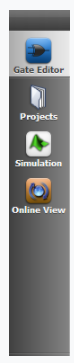
- Gate Editor

On Mikrodiagram, it is mode of project preparation.
- Projects
"Device configuration, PLC and extensions, text table, block properties table, variable address table, display options and IEC61850 table" options.
- Simulation

On Mikrodiagram, provide you to test the prepared projects in offline mode without loading the device and examine the program responses.
- Online View

It is used to track block values and load new values into blocks by USB or TCP connection to Mikrodiagram project loaded on the device.
Build Mode Options

Build mode options can be switched to "connect / disconnect device, compile project, send to binary device, send project to device and project selection" modes.
- Device Connetion/ Disconnetion

Used to establish a connection between the device to be programmed and the computer. USB or TCP port connectivity options are available.
- Build Project

On Mikrodiagram, it is used to compile the prepared project.
- Send Binary to Device

Used to send binary files to the device.
- Send to Device

Used to send the prepared project to the device.
- Project Selection

On Mikrodiagram, if more than one project is open it is used to select the project to be sent to the device.
Sidebar Options
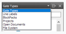
You can switch to the "block types, line labels, block packages, projects, open diagrams and file system" modes from sidebar options.
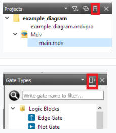
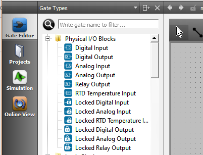
- Gate Types
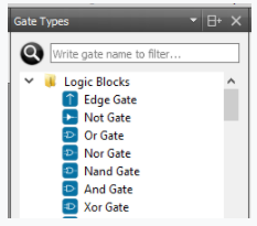
On Mikrodiagram , in order to select the blocks used for FBD programming and move the blocks to programming age, it is necessary to select "Gate Types".
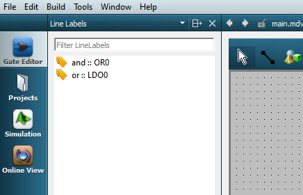
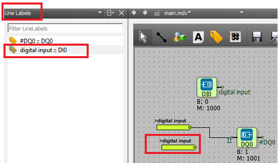
- Line Labels

While "line labels" is selected in the sidebar, "line definitions" defined in Mikrodiagram can be displayed and used in the project.
- Projects
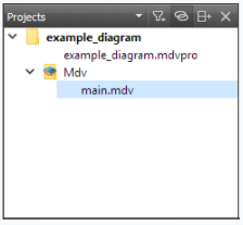
While "line labels" is selected in the sidebar, open projects are displayed, and projects are selected.
- Split
It can be divided into sections using the "split" option to select more than one mode in the sidebar.
Mikrodiagram Configuration
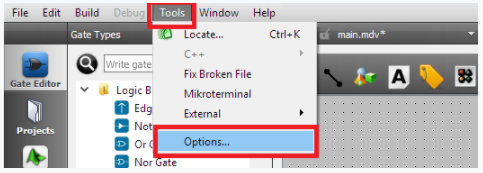
Mikrodiagram configuration can be accessed by clicking on "Options" on the "Tools" menu. "environment, text editor, diagram editor and version control" are available.
Environment
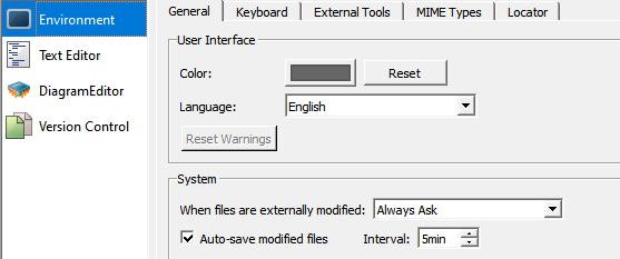
On the environment tab, there are "general, keyboard, external tools, MIME types and locator" options.
- General
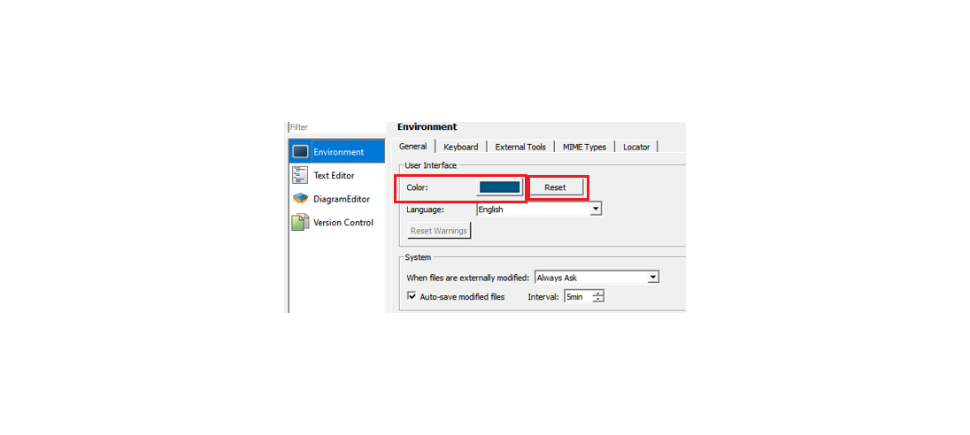
From the General tab, Mikrodiagram interface color can be changed and the color settings can be reset. (Return to factory settings.)
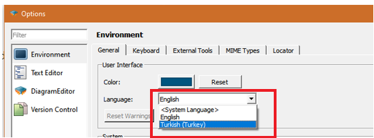
Mikrodiagram have Turkish and English languages options.
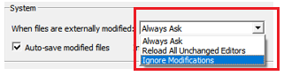
If the files are changed from the outside in Mikrodiagram, the application status of the changes is checked.
Mikrodiagram needs to be restarted when selecting between language options.

When it is desired to automatically save changes made to the project in Mikrodiagram, the "modified files can be saved automatically" can be selected and the time interval to be saved can be specified.
- Keyboard
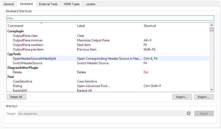
It provides access to the factory settings of the shortcut keys used in Mikrodiagram on the keyboard tab.
The shortcut key settings can be changed and the factory default settings can be restored.
- External Tools
- MIME Types
- Locator
Text Editor
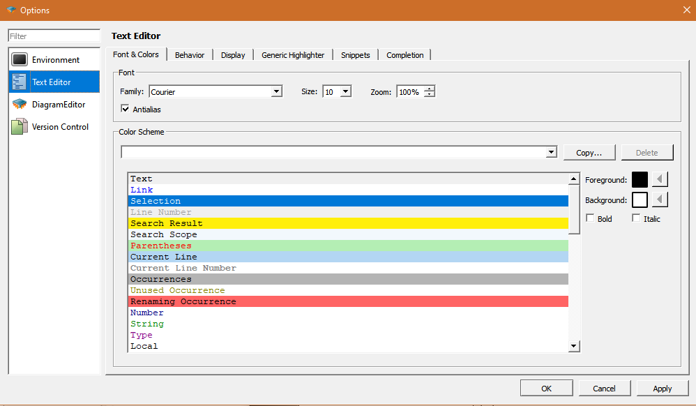
The current status of the fonts used in Mikrodiagram is displayed.
With the font&colors, behavior, display, generic highlighter, snippets, completion options, the appearance of the text editor can be edited.
Diagram Editor
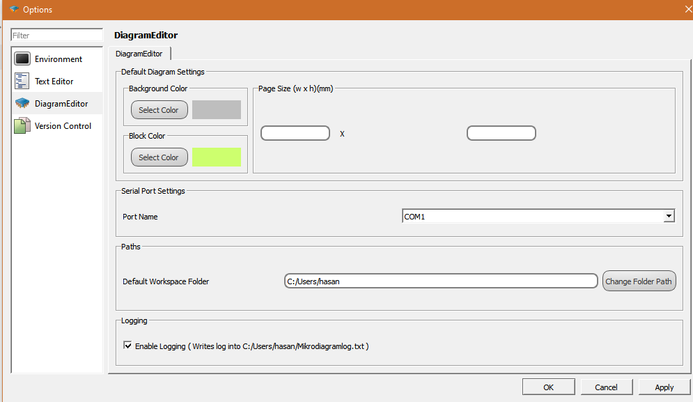
It is used to make settings for Mikrodiagram background color, block color, page size and USB port selection
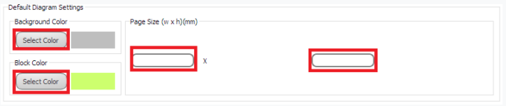
It can be adjusted by selecting color from "background color" section in Mikrodiagram.
It can be adjusted by selecting color from "block color" section in Mikrodiagram.
Page sizes can be set to any size.

It is used to make COM port selection from Mikrodiagram to serial port connection to device.

The "logging" to save newly created projects is selected.
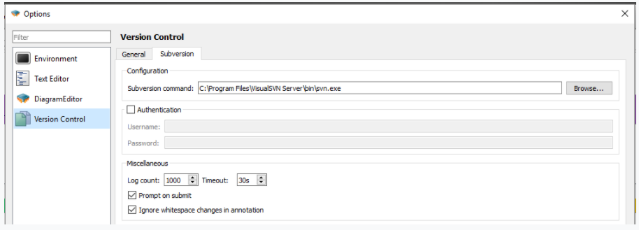
Version Control
General
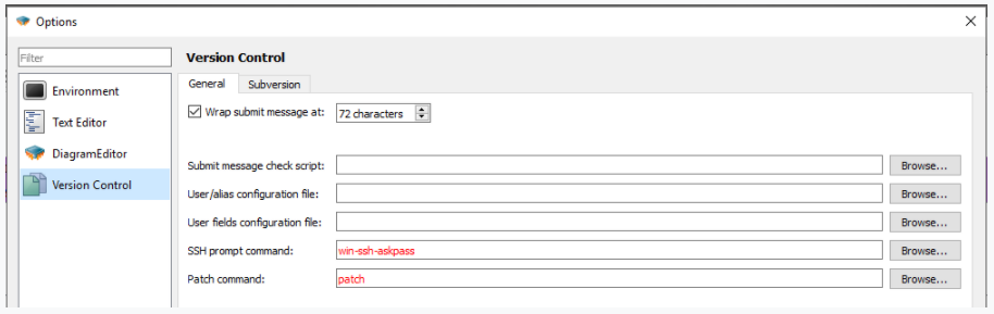
Subversion
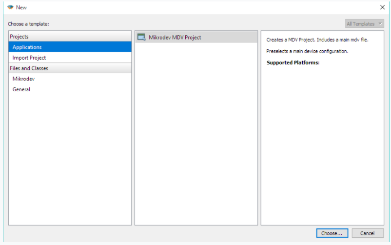
Creating A Project
![]()
To create a new project in Mikrodiagram, select "New file or Project open " in the "File Menu".
- Step 1
- Step 2

The newly created project name and project creation place are selected
When "Use as default project location" is selected, project creation place is fixed for the projects to be created later.
- Step 3
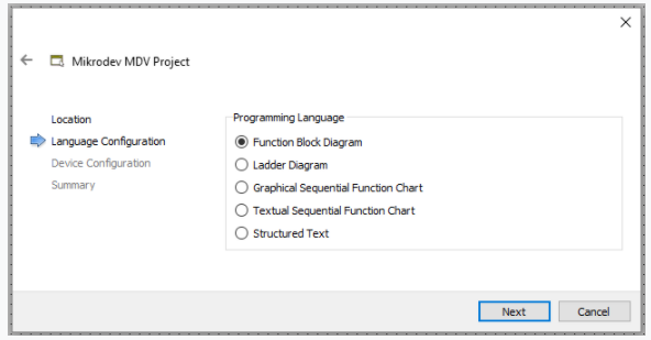
Programming method selection is done.
- Step 4
The device to be programmed and the expansion unit if required are selected.
- Step 5
Project configuration settings can be changed.
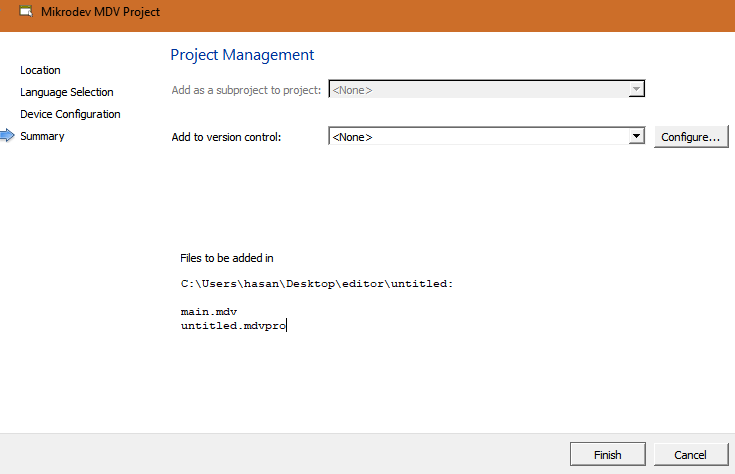
- Step 6
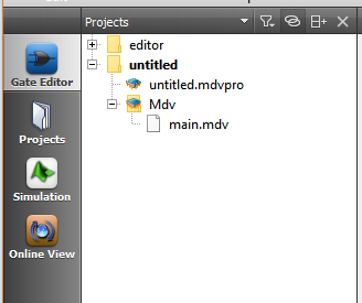
A new project has been created.
Project design can be started on the page opened by clicking on the file "main.mdv".
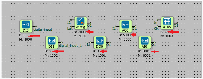
Using Editor
Block Inserting (Gate Type Inserting)
Mikrodiagram-specific FBD (function block diagram) can be programmed with door types keep in the programming library.
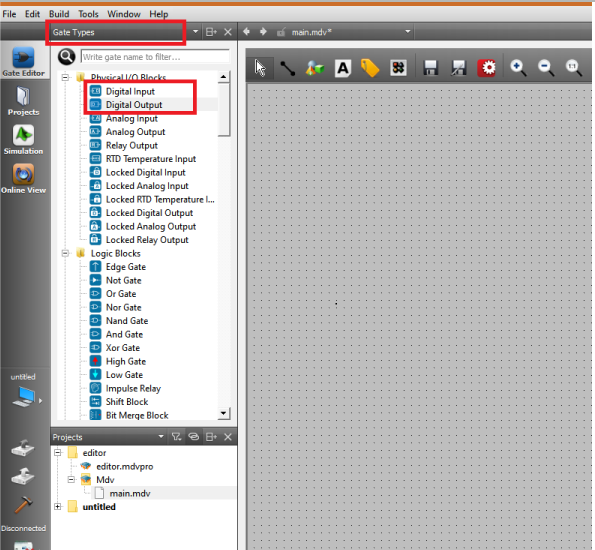
"Gate Types" are selected from the sidebar and the door type to be added is selected.
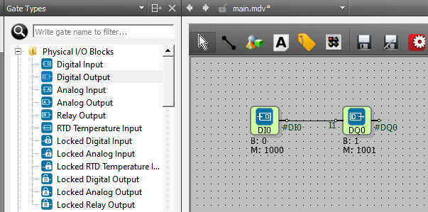
The door type to be added is clicked, then the door type is moved to the work area when it is clicked on the work area. The input and output of the added blocks are connected to each other and the design of the project is continued.
Inserting Line Label
In projects of Mikrodiagram can be made programming by connecting block outputs to inputs of other blocks.
Another way to connect block outputs to the inputs of other blocks is to add a line label.
Any block named "line definition" can be used as a line tag when connected to a block.
Line labels facilitate the preparation of projects and increase the readability of the projects.
- Step 1
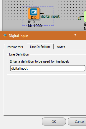
To move any block output to another point with a line tag, double-click on the block to access "object properties". The "line description" tab in the object properties is clicked, and a description is written in the line tags.
- Step 2

The "line tag" is added when clicking on the "add line tag" icon in Mikrodiagram status bar and then clicking on the work area. The output of the line tag is connected to the block input, as is the method of connecting the blocks together.
- Step 3
![]()
Double-click on the line label to select from line definitions.
- Step 4
Another way to add a line tag is;
The "line tags" are selected from the sidebar. A "line tag" can be added to the work area by selecting from the line definitions defined in the project.
There is also a filtering feature to choose from line tags.
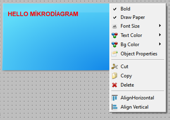
Inserting Text
It is used to add notes to project creation area in Mikrodiagram. The fonts and background of the added notes can be changed.
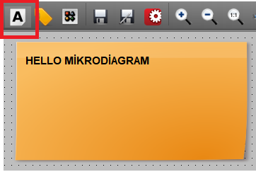
If you click on the "insert text" button in Mikrodiagram status bar and then click on the work area, the memo page to be added is moved to the work area. The notes can be written on the note sheet. Font, color, background etc. to change the settings right-click on the note and make selection.
Grinding Of Blocks
Mikrodiagram block grouping feature; it facilitates the follow-up of the functions of the block groups in the projects.
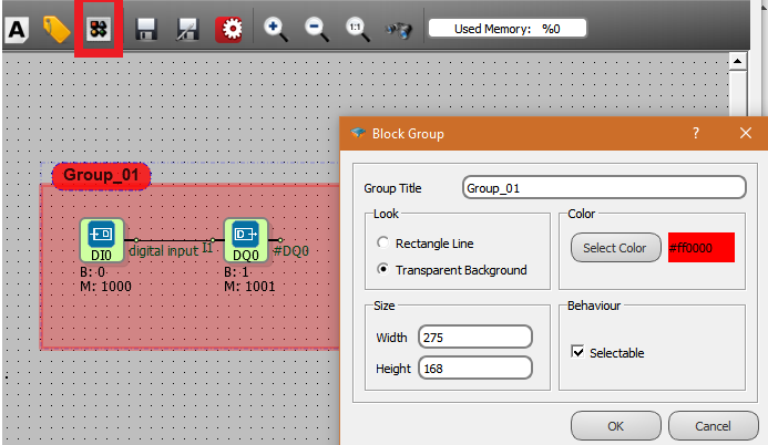
Click on the "Block Group" icon in the status bar, then the blocks are grouped in the work area using the select-and-drop method.
The block grouping properties page is reached by double clicking on the block grouping.
The name of the block group is defined by "group title" option.
With the "Look" option, the background of the block group (transparent background or rectangular line) is selected.
With the "Color" option, the desired color selection is made for the block group.
The size of the block group is adjusted by "Size" option.
In the "Behavior" option the selectivity status of the block group is determined.
Diagram Settings
In Mikrodiagram, it is used to adjust the dimensions of the pages on which the projects are created.
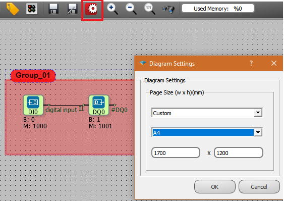
In the diagram settings, page sizes can be selected from standard A3, A4, A5, A6, as well as making custom settings for the programmer.
Gate Editor
In the "gate editor" section of the mode options, the project creation page is accessed
Object (Block) Properties
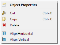
Block properties are reached by right clicking on the blocks added in Mikrodiagram. Block features include "object properties, cut, copy, delete, align horizontal, align vertical " properties.
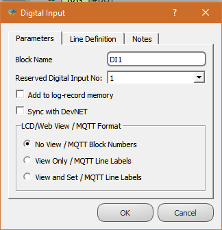
- Object Properties

In the block object properties, there are "parameters, line definition and notes" windows.
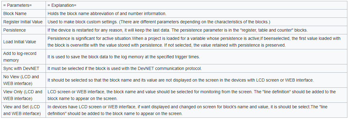
- Parameters
The parameter definitions are explained in the table.
- Line Definition
Block outputs are used when you want to be identified by a name determined by the programmer. Line definitions have multiple uses.
1 - The "line definition" is used in the blocks where the outputs are to be connected with the "line label" to the entrance of another block.
2 - If the block value is to be monitor and changed from devices with LCD screen feature or WEB interface."line definition" should be added
3 - If the blocks in Mikrodiagram will be defined in the "variable address table", the "line definition" must be added to the blocks.
- Notes
It is used by the user to write notes into the block.
- Cut-Copy-Paste-Delete

Cut-copy-paste-delete operations can be performed on the blocks used in Mikrodiagram project. Cut-copy-delete operations can be done by right clicking on the block. For the "Paste" option, right click on an empty area in Mikrodiagram workspace and select the "paste" option.
- Align Horizontal-Align Vertical
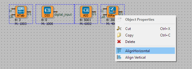
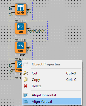
It is used to scale the selected block group horizontally or vertically in Mikrodiagram.
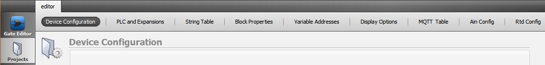
Project Configuration
In Mikrodiagram, project-specific configurations can be made from the "projects" section in mode options.
Device Configuration
Connected to device on TCP when, is used for Ip ,port, version etc. settings making and viewing
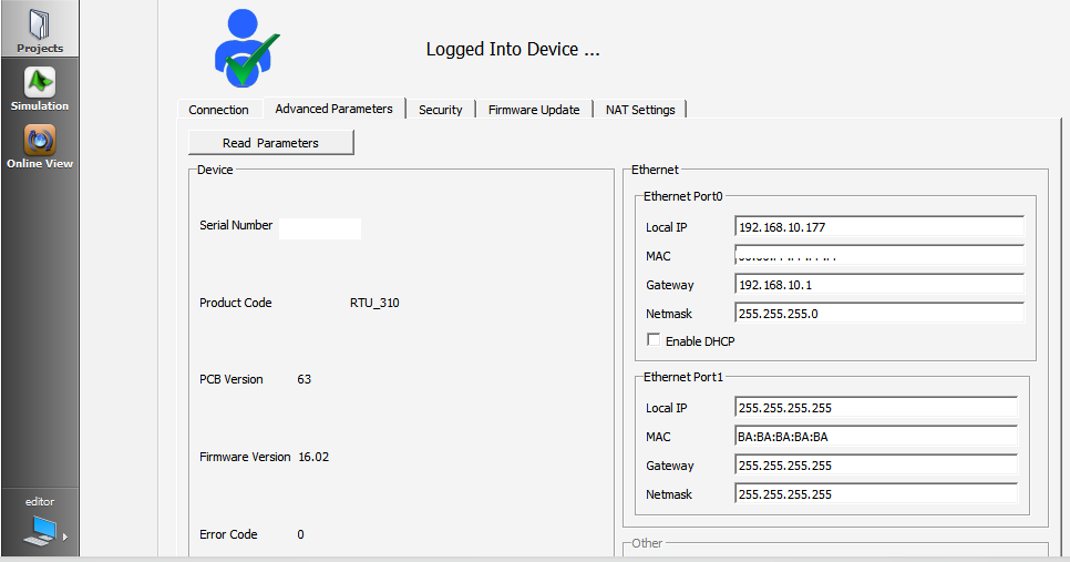
- Connection
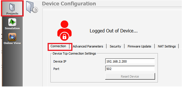
It is used to establish a connection to the device over the TCP port and to restart the device with the "Restart device" button on the TCP port.
In the "Device IP" section, the IP address of the device to which the TCP connection is to be made is written in. If a connection from a local network, connection from an external network, or connection to a GSM device will be established, appropriate IPs must be defined.
Port: The listening port identification of the device should be done. The standard listening port 502 in Mikrodev products. It can be changed.
In order for the "Restart device" button to be active, the TCP connection must be established.
- Firmware Update
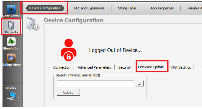
After the TCP connection is established, use the name of the device embedded software you want to update.
- Advanced Parameters
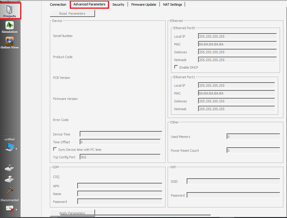
After the TCP connection is established, it is used to configure the device's version, IP, port, clock etc. settings. "Read parameters" are used to read the parameters, and "apply parameters" buttons are used to set the parameters.
When "apply parameters" is selected while "Sync Device time with PC time" is selected, the computer clock is written to the device.
In order to be able to set parameters of the GSM section, the device must be GSM supported product.
After making the settings with "Apply parameters", the device needs to be restarted.
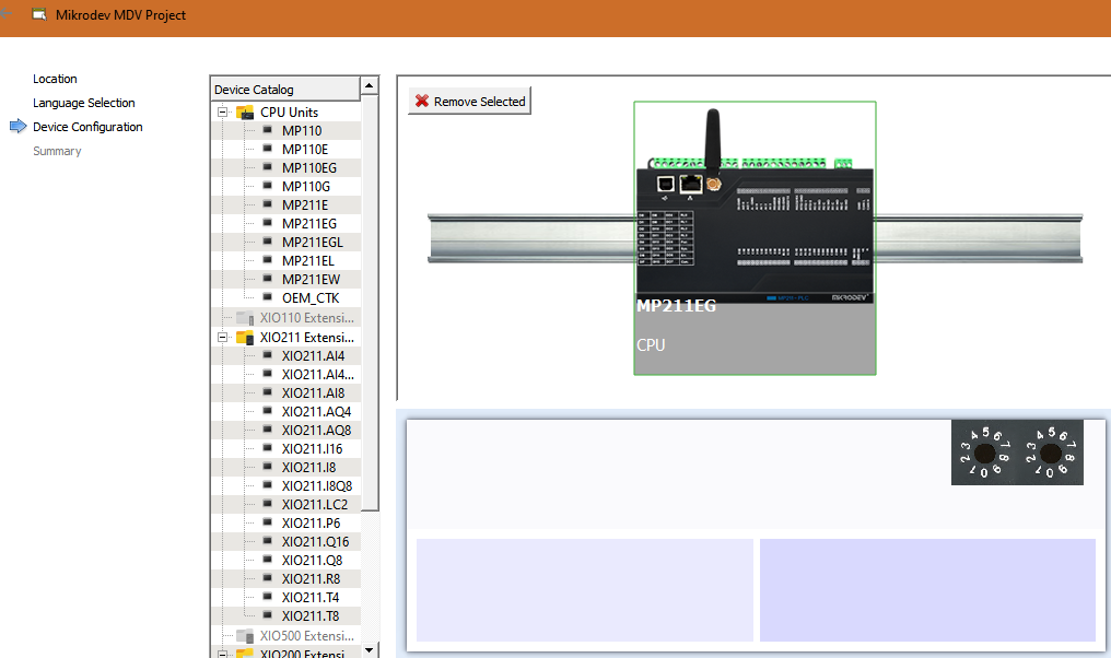
PLC And Expansions
The devices used in the project are selected.
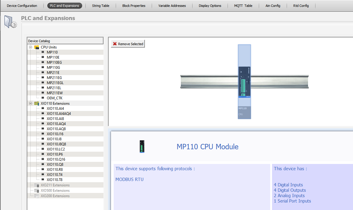
- Update CPU Module
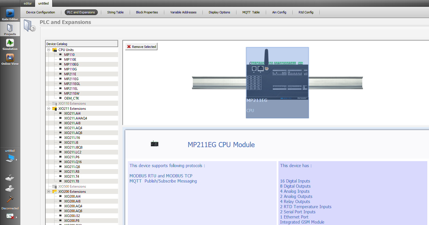
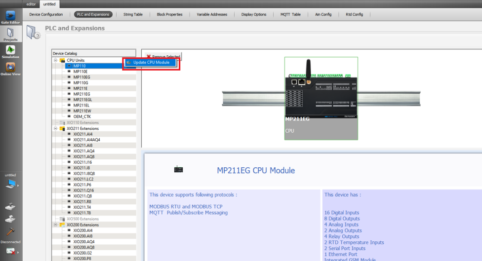
The device to load Mikrodiagram project is selected. The main unit to be used in the project is clicked, the "Update CPU Module" tab is clicked to select from the devices.
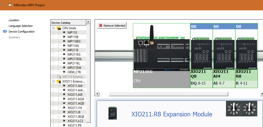
- Add Extension Module/Remove Selected
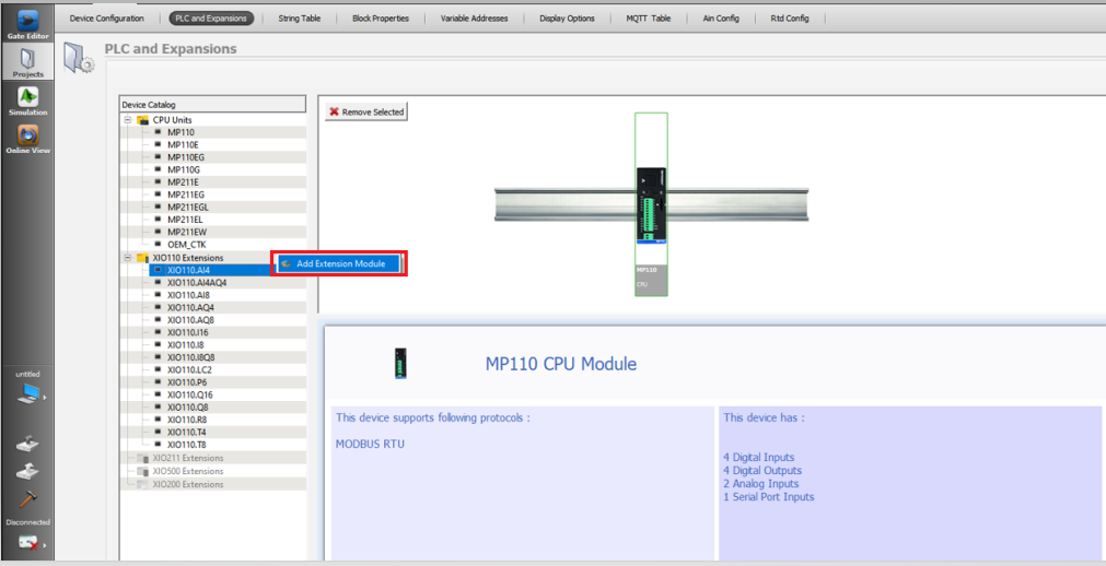
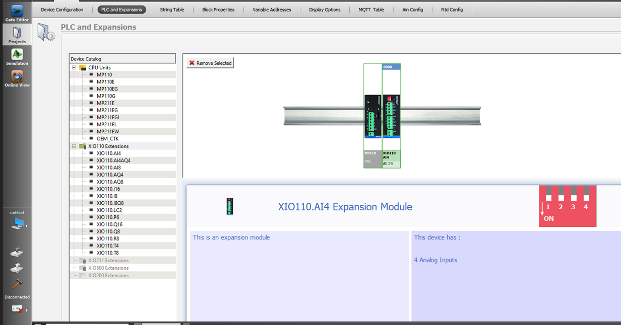
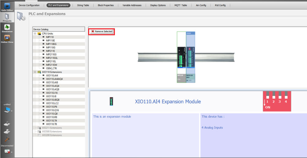
If the number of physical inputs / outputs used in the prepared project is more than the number found on the main unit, it is necessary to add expansion units to the project.
Click on the relevant module in the Extension Devices section, click on the "Add Extension Module" tab to add. When the extension unit to be added is desired to be removed, the relevant unit can be clicked and the "Remove Selected" or "delete" key can be pressed.
For example, MP211 PLCs have 16 digital inputs (DI). If more than 16 digital inputs are used in the prepared project, it is necessary to add digital input expansion unit (XIO211.I16).
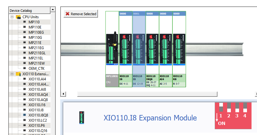
- Incompatible Device Error Code:18
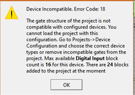
If a mistake is observed in loading the prepared project into the device, the number of physical inputs and outputs used in the project is more than "main unit and selected units".
The MP211 PLC and 8 digital input expansion modules (XIO211.I8) have been added to the project in the above line. A total of "digital input" door types have been added to the project. However, since the digital input expansion module (XIO211.I8) "extract the selected unit" was made, the "incompatible device error code: 18" error occurred when loading the project into the device.
The digital input expansion (XIO211.I8) unit must be added again in order to avoid the error.
String Table
While SMS and DTMF search features are used in GSM products , SMS content and phone number are used for identification.
There are 64 lines in the text table and 64 characters per line.
Turkish characters should not be used in the text table.
The definitions in the text table must be selected from "text blocks" for use in SMS and DTMF searches.
String Text
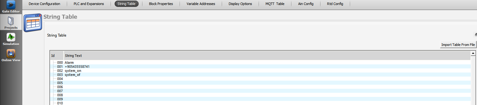
Definitions in the text table The Mikrodiagram project is loaded into the device when it is sent to the device.
The way in which phone numbers are written in text contents may differ according to GSM operators (some operators support numbering with country phone codes as (+905001234567), others without country phone codes. (05011234567)).
No spaces between words when writing text content.
Block Property Table
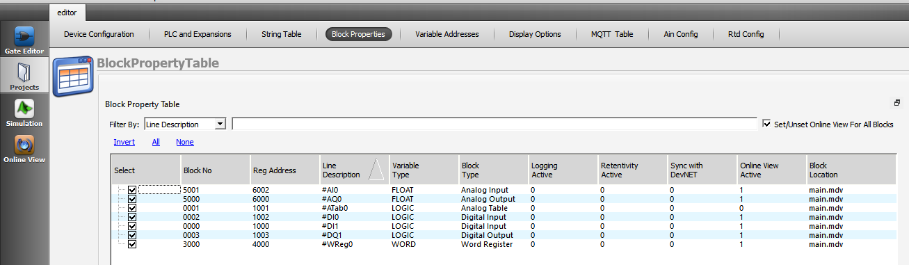
Block number of blocks, register addresses and variable types added to the project prepared in Mikrodiagram are used for easier definition of line definitions, logging and online monitoring situations.
There is also the possibility to export the table to CSV and Excel.

- Select/Export Selected Blocks to CSV and Excel

It is used to transfer the selected blocks to CSV and Excel.
With the "Invert" tab, the selection of blocks is reversed.
All blocks are selected with the "All" tab.
With the "None" tab, the selections in all blocks are removed.
- Block No

It is used to monitor block numbers of door types and to transfer them to CSV.
- Reg Address

It is used to monitor modbus communication addresses of door types and to transfer them to CSV.
- Line Description


It is used to modify and follow line definitions defined in blocks.
The line definitions can be changed from the block object properties and the block properties table.
- Variable Type

There are 4 types of variables in Mikrodiagram: logic, word, float, long type. It is used to monitor and transfer variable types of blocks to CSV.
- Logging Active& DevNET

It can be selected from the block object properties and the "Add log record to memory and synchronize with DevNET" options can also be changed from the block properties table.
- Online View Active
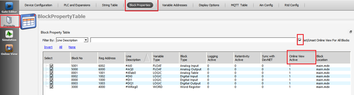
It is possible to select the blocks to be watched and changed in the program via USB or TCP port. With "Turn on / off online monitoring for all blocks", online monitoring can be activated for all the blocks in the program, as well as the blocks that need to be monitored from the "online monitoring active" section can be selected.
Variable Address Table
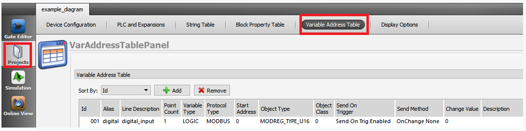
- Descriptions
1- In DNP3, IEC101 and IEC104 protocols, variable addresses, types and data transmission methods are used.
2- It is used in Modbus Protocol when it is desired to define a different Modbus address than the standard modbus register addresses on the blocks.
3- It can be used to read data recorded in table blocks starting from a specified address determined by TCP communication.
4- In Mikrodiagram, "block definition" must be made to blocks so that blocks can be defined in variable address table.
- Alias

It is used naming for blocks transferred to the table.
- Start Address

It is used for variable address definitions.
If MODBUS is selected as the protocol type, the selected start address must be selected differently from the block addresses used in Mikrodiagram. (Variable addresses in Mikrodiagram, word: 4000, binary: 1000, analog: 6000, long: 8000).
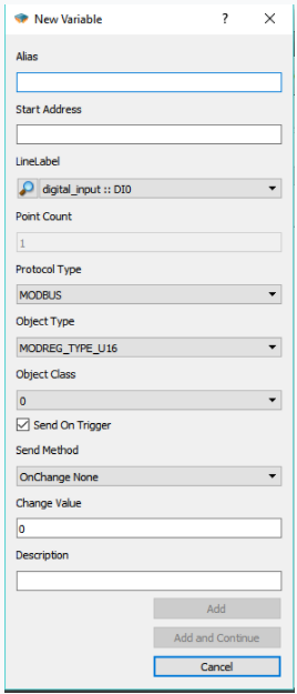
- Line Label

Block selection is made, defined in the variable address table.
In Mikrodiagram should be defined "line definition" to blocks to be transferred to the variable address tab.
- Point Count

The number of addresses to be identified from the starting address added to the variable address table is determined. If table blocks are added to the variable address table, the number of points to be read according to the size of the table is automatically defined. (If the starting address is 10000 and the dot number is 4, the defined addresses are 10000, 10001, 10002 and 10003.)
- Protocol Type

Communication protocol type selection of blocks transferred to variable address table is configured.
- Object Type

Object (variable) types that differ in each protocol are selected.
- Object Class
![]()
Object classification definitions
- Send Periodically
![]()
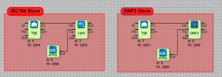
In DNP3, IEC 101, IEC104 protocols, the data added to the variable address table at specific time intervals are used to sending to client of the datas. For example, if a trigger is detected for 10 seconds on the side of the IEC slave block and the defined block in the variable address table is "send on trigger"; The block value is sent to the client at intervals of 10 seconds.
- Send Method/Change Value


In DNP3, IEC101, IEC104 protocols, the block values defined in the variable address table are used sending to client the when the change exceeds the specified value according to the determined change method. For example, if the sending method is "change level" and the change value is 4, then the value client is sent if the difference between the first value and the value to be sent is greater than 4. (If the first value is 15 and the last value is less than 11 or greater than 19, is sent.
Note:
IEC101, IEC104, DNP3 protocols are not supported in Mikrodev PLC Devices.
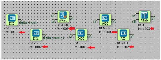
Display Options
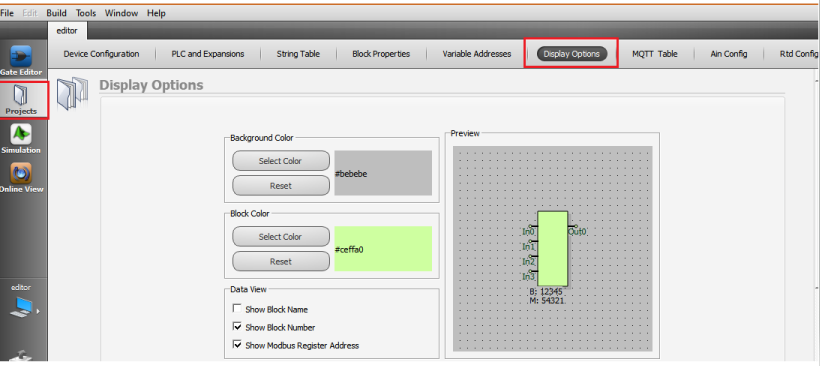
In Mikrodiagram,changing the project working background and block colors; is used block name, block number, and register addresses on blocks. The settings are project-specific. Different settings can be used in each project.
- Background Color
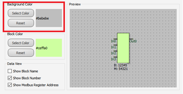
The Mikrodiagram workspace background colors can be changed and reset to their initial settings.
- Block Color
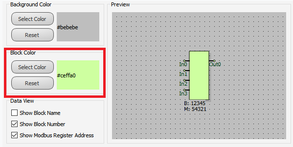
Mikrodiagram block colors can be changed, reset to initial settings.
- Data View
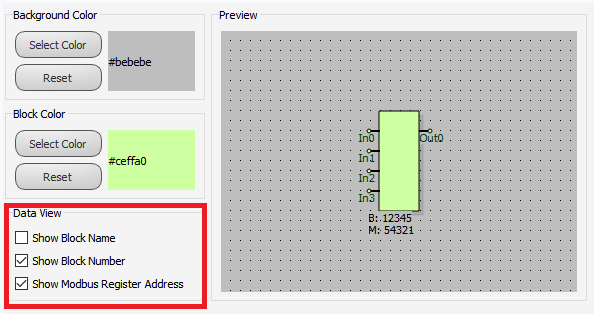
It can make block name, block number and modbus register addresses selection of display status on the block.
MQTT Table
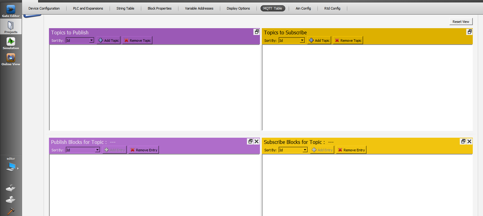
Topics The Publish
In this table, the Publish topic is entered to publish the data to the broker. The topic name is entered on the screen that appears by pressing the Add Topic button in the table. Block definitions where you can enable/disable Qos, Retain, Last Will, Payload settings, send on exchange and periodically send options are also made on this page.
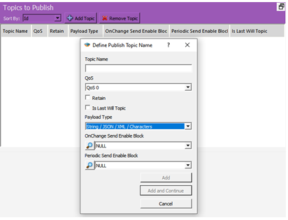
Definitions;
• Topic Name: The field where the topics you will send the messages are determined.
• QoS: Quality of Service refers to the agreement between the sender of a message and the receiver of the message. The QoS levels are as follows;
o QoS 0: Minimum data transfer is ensured. At this level, each message is forwarded to a subscriber and no confirmation is received that the message has arrived.
o QoS 1: The broker tries to transmit the message and waits for an acknowledgment response from the subscriber, if no confirmation is received within a specified time frame, the message is sent again.
o QoS 2: The broker receives two acknowledgments to ensure that the subscriber receives the message and only once.
• Retain: If this option is checked, if the connection between the broker and the subscriber is broken, the last value will be saved in memory.
• Is Last Will Topic: Last will topic. If a topic is created and this option is checked, the message under this topic will be forwarded to the subscribers when the device is disconnected from the broker.
• Payload Type: It is determined in which format the message content will be sent. Subscriber interprets incoming messages with this information. “MJson v1” can be selected if a time stamp is desired to be added to the sent messages.
• On Change Send Enable Block: Block selection added in the diagram to enable or disable the sending feature of the created topic on change.
• Periodic Send Enable Block: Block selection added in the diagram to enable or disable the periodic sending feature of the created topic.
Publish Blocks for Topic
In this table, the blocks to be published for the relevant Topic are selected. After clicking the topic in the Publish to topic table, the Add Entry button becomes active and by pressing this button, the block to be published in the project is selected. How to transmit the data can also be selected from the screen.
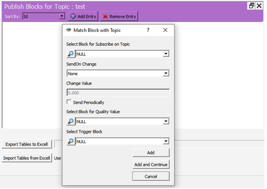
Definitions;
• Select Block for Subscribe on Topic: The area where the block that you want to send as a message in your project is selected.
• Send On Change: Send selection field on exchange
o On Level Change: Send when there is a change in the value specified in Change Value, if 0 is written, it will be sent in every change.

o On Percent Change: Send when there is a percentage change of value specified in Change Value, for example 10%.
• Change Value: Change amount input field.
• Send Periodcally: If checked, a message is sent every time a trigger comes to the trg input of the mqtt config block.
• Select Block for Quality Value: The block in which the Quality value included in the message content is selected in MJson v1 payload type.
• Select Trigger Block: Apart from change or periodicity, we can send the message by triggering the block we will specify here.
Subscribe to Topic
In this table, the relevant subscribe topic is entered to send data from the broker to the device.
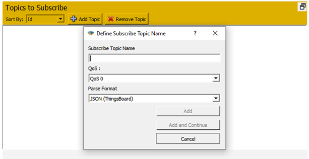
Definitions;
• Subscribe Topic Name: Enter the name of the topic to be subscribed to.
• QoS: Service quality level is selected.
• Parse Format: Select the format in which the messages will be parsed.
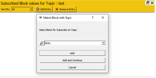
Subscribed Block Values for Topic
From this screen, the blocks to be associated for the subscribe topic are added. To use line tags, mqtt format should be selected as view and set from the special settings of the relevant block.
Simulation

The projects prepared in Mikrodiagram are tested without loading in the device and used in monitoring the reactions.
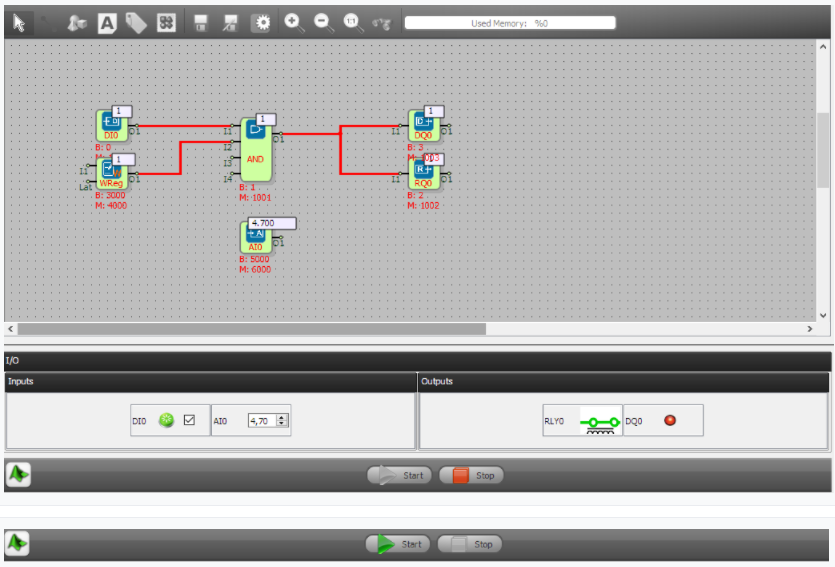
- Descriptions
To run the project prepared in Mikrodiagram in simulation mode, click on "simulation" from "mode selection".
Start the simulation with the Start button.
Values are written from "inputs" section to digital and analogue inputs. Digital and analog outputs, "output" section can be monitored.


Assigning values to variables process (word, long, analog, binary register, etc.) is done from the displayed window by right clicking on the corresponding block.
Block status and values are monitored over blocks in simulation mode.
= Note:= Simulation mode is not active in some blocks such as communication blocks, motion control blocks, GSM blocks.
Online View

The projects prepared in Mikrodiagram are used after uploading to the device, monitoring the responses using USB or TCP port connection and assigning new values to the blocks.

- Cyle Periods(ms)

It is used to determine the cycle time of online view.At the specified time intervals, online monitoring is performed on the blocks, the block values are read and written over the blocks.
- Descriptions
The processes to be followed in order to get the project prepared in Mikrodiagram to "online view" mode;
1 - The selection of the blocks to be monitored online should be made under the heading "Online view active" in the "block configuration" tab in the "project configuration" section.


Selection of blocks to be monitored online can be done by right clicking on the block after loading Mikrodiagram project on the device and "enable / disabe online view".
2 - USB or TCP port connection is established.
3 - Prepared Mikrodiagram project is loaded on the device.
4 - Reconnect the USB or TCP port.
5 - In the mode selection, click on "online view" and the "cycle periods" is set.


Click "Start" to start online monitoring.
The red-blue colors flash on the blocks for which online monitoring is active.
- Connecting To Device

It is necessary to connect the device to send the project prepared in Mikrodiagram to the device and to monitor online.
Mikrodiagram can be connected to the device via USB or TCP port.
Mikrodiagram can not be connected to USB and TCP port at the same time.
Usb Connection
In order to use the USB connection, installation of the USB driver should be completed.
There is no need to install a USB driver on computers with Windows10 or higher operating system.
After the USB Driver installation is complete, a USB cable is connected between the computer and the device.
"USB A and USB B" (printer cable) should be preferred when selecting USB cable. The USB B side is connected to the device and the USB A side is connected to the computer.
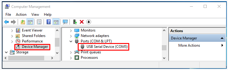
The COM port from which the USB cable connecting from Device Manager is defined is determined.
Connetion interface is accessed by clicking the tab in the build mode options.


"Connect using SERIAL USB" is selected, COM port selection is made. "OK" button is started the connection process.
When the “A USB connection is established between the device and computer on serial port COM8” warning is received and the connection button reaches the "connected" position, the connection via USB is completed.
TCP Connection
In order to establish a TCP connection between the computer and the device;
At least one of the "Ethernet, Wi-Fi or GSM" ports must be found in the device to be connected to the TCP.
Establishing a TCP Connection with Ethernet
For the Ethernet connection to be established;
1 - The device must be an ethernet port.
2 - The ethernet cable (CAT5, CAT6) connection must be established between the device and the computer.
3 - If the device and the computer are on the same local network, the defined IPs must be selected accordingly.
Defining IP to Device
The "Mikroterminal" program must be used to make device IP settings via USB connection. (See section "Using Mikroterminals".)
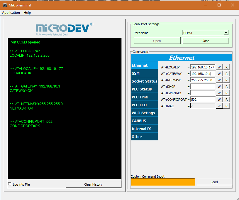
Mikroterminal application can be accessed from Mikrodiagram "Tools" menu.
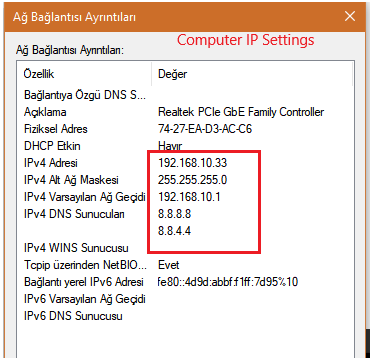
After the device and computer IP settings are complete, the device must be "pinged" from the computer for the "ethernet cable connection test" between the device and the computer.
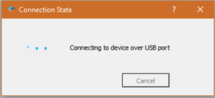
For the "pinging" operation, the computer is typed in the "command window", the device IP is shown in the picture and "ENTER" is clicked.
If the resulting output in the top image occurs, the ping operation is "unsuccessful". IP settings and ethernet cable connections should be checked again.
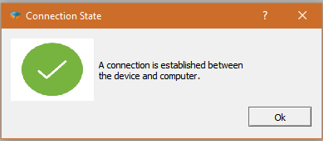
If the result output looks like the following figure, the ping operation is "successful".
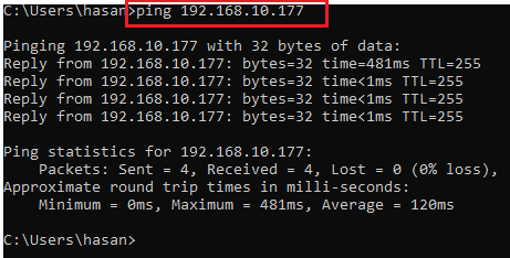
An ethernet TCP connection can be established from Mikrodiagram to the device.
- Defining Listening Port to Device
The standard listening port 502 in Mikrodev products is defined as.
To change the default listening port 502;
1- A TCP socket block should be added to the project prepared in Mikrodiagram.
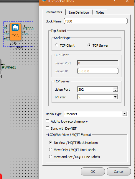
2- Socket type "TCP server" is selected.
3- Listen port is defined.
4- Select "Ethernet", "GSM" or "Wi-Fi" as the "Media type".
Note: The listening port can be defined by the number of TCP socket blocks added as a server in Mikrodiagram project.
- Ethernet Connection Test
After making the necessary settings for Ethernet connection, for TCP connection;
1 - The link in the Build mode options is clicked on the tab.

2 - Click "Settings" in the window that opens.

3 - In the window that opens, "Device IP" section is device IP and device listen port is write in "Port" section.
4- Select "Connect using TCP" and click "OK" to install TCP connection.
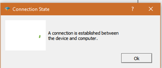
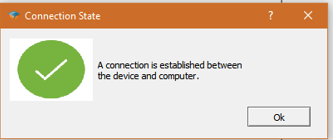
5- When the TCP connection is established, a warning "A TCP connection is established between the device and computer" appears on the screen.
The link icon is displayed as "Connected" .

- Establishing a TCP Connection with GSM
In Mikrodiagram,GSM with the for installing TCP connection to the device;
1 - The device must have GSM-enabled .
2 - GSM antenna of the device should be connected.
3 - The device signal quality (CSQ) must be between 1 and 31.
4 - SIM card with data package (internet package) should be inserted into the device. (The SIM card must have a fixed IP address.)
5 - APN identification of the inserted SIM card should be done to the device.
6 - The Mikrodiagram installed computer must be connected to the "wide area network" (WAN) (internet network).
- Defining IP to Device
In order to establish a TCP connection from Mikrodiagram to the GSM-enabled device,to the "device IP" section is written in IP of GSM.

Other operations outside the GSM IP definition are identical to the Ethernet TCP connection.
Loading The Mikrodiagram Project To Device
There are 2 methods to load the project prepared in Mikrodiagram into the device.
The project can be sent to the device via USB or TCP connection.
Loading Project With Usb Connection
USB connection between device and computer After connection is establishment, click on the "send to device" button.

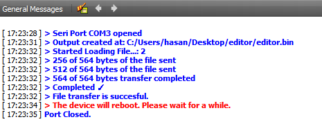
If the output is as follows in the section "General Messages" in Mikrodiagram, then Mikrodiagram project is successfully loaded into the device.
Care must be taken to ensure that the file upload process is 100% complete.
With the USB connection, the device restarts automatically when the project uploading process to the device is 100% complete.
Loading Project With Tcp Connection
TCP connection between device and computer After the connection is establised, clicked on the "send to device" button.


The project loading process must be waited to be 100% complete.
Unlike the case of loading the project with USB, device restart is performed manually.

After the project loading process is completed 100%, click "connection" from the "device configuration", click "restart device" and the project loading process is completed.
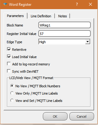
Retentivity Configuration
When designing a PLC application, it is important for the PLC user to understand the different types of memory in the PLC. Three types of memory are used by the Mikrodev PLC; RAM, SRAM and FLASH memory.
SRAM memory can be configured by the PLC user as either retentive memory. SRAM is powered by internal battery when PLC external power is off.
Retentive memory is memory that is configured by the user to maintain values through a power reset. Non--retentive memory is memory that is configured by the PLC user to clear data after a power reset.
The default behaviour of the blocks in Mikrodev PLC is non-retentive. You need to select "Retentive" option to make the block use retentive memory.
- Example: 1
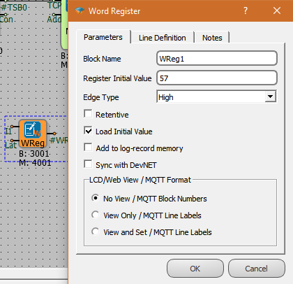
If “Retentive” is not selected, it does not make any difference whether you select “Load Initial Value” or not.
On Power Reset: The device will load the “Register Initial Value” into the register.
On Project Upload: The device will load the “Register Initial Value” into the register.
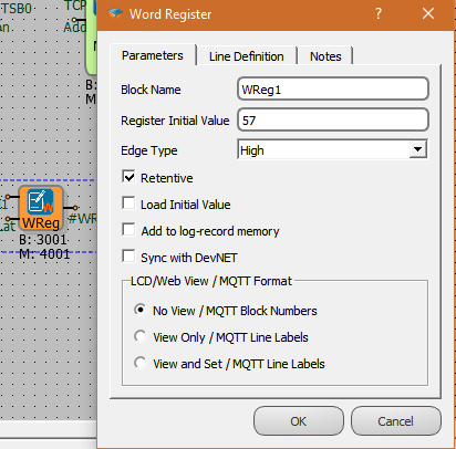
- Example: 2
On Power Reset: The register will preserve the latest value. On Project Upload:
A- If there are any changes in the project like adding/removing retentive blocks, the “Register Initial Value” will be written on the register after boot.
B- If there are minor changes on the project like parameter update or add/remove lines, the register will preserve the latest value after boot
- Example: 3
On Power Reset: The register will preserve the latest value. On Project Upload: “Register Initial Value” will be written on the register