Telediagram Editor
Using IEC 104
IEC 60870-5-104 is a protocol for power system monitoring and controlling. Mostly used to communicate between substations and control centers over Ethernet (Fiber optics, 2/3/4G, ...). IEC 60870-5-104 protocol is an extension of IEC 60870-5-101 protocol with the changes in transport, network, link and physical layer services to suit the complete network access.
Here you will find basic information about protocol parameters:
- APCI - Application Protocol Control Information
- APDU - Application Protocol Data Unit
- ASDU - Application Service Data Unit
Address
- IP address - every device in Ethernet have physical address
- ASDU address - every slave (client) device has a logical address, also one device could have more than one ASDU address
- IOA address - information object address
| Dec | Type | Description | Direction |
|---|---|---|---|
| 1 | M_SP_NA_1 | Single-point information | Monitor |
| 2 | M_SP_TA_1 | Single-point information with time tag | Monitor |
| 3 | M_DP_NA_1 | Double-point information | Monitor |
| 4 | M_DP_TA_1 | Double-point information with time tag | Monitor |
| 5 | M_ST_NA_1 | Step position information | Monitor |
| 6 | M_ST_TA_1 | Step position information with time tag | Monitor |
| 7 | M_BO_NA_1 | Bit string of 32 bit | Monitor |
| 8 | M_BO_TA_1 | Bit string of 32 bit with time tag | Monitor |
| 9 | M_ME_NA_1 | Measured value, normalized value | Monitor |
| 10 | M_ME_TA_1 | Measured value, normalized value with time tag | Monitor |
| 11 | M_ME_NB_1 | Measured value, scaled value | Monitor |
| 12 | M_ME_TB_1 | Measured value, scaled value wit time tag | Monitor |
| 13 | M_ME_NC_1 | Measured value, short floating point number | Monitor |
| 14 | M_ME_TC_1 | Measured value, short floating point number with time tag | Monitor |
| 15 | M_IT_NA_1 | Integrated totals | Monitor |
| 16 | M_IT_TA_1 | Integrated totals with time tag | Monitor |
| 17 | M_EP_TA_1 | Event of protection equipment with time tag | Monitor |
| 18 | M_EP_TB_1 | Packed start events of protection equipment with time tag | Monitor |
| 19 | M_EP_TC_1 | Packed output circuit information of protection equipment with time tag | Monitor |
| 20 | M_PS_NA_1 | Packed single point information with status change detection | Monitor |
| 21 | M_ME_ND_1 | Measured value, normalized value without quality descriptor | Monitor |
| 30 | M_SP_TB_1 | Single-point information with time tag CP56Time2a | Monitor |
| 31 | M_DP_TB_1 | Double-point information with time tag CP56Time2a | Monitor |
| 32 | M_ST_TB_1 | Step position information with time tag CP56Time2a | Monitor |
| 33 | M_BO_TB_1 | Bit string of 32 bit with time tag CP56Time2a | Monitor |
| 34 | M_ME_TD_1 | Measured value, normalized value with time tag CP56Time2a | Monitor |
| 35 | M_ME_TE_1 | Measured value, scaled value with time tag CP56Time2a | Monitor |
| 36 | M_ME_TF_1 | Measured value, short floating point number with time tag CP56Time2a | Monitor |
| 37 | M_IT_TB_1 | Integrated totals with time tag CP56Time2a | Monitor |
| 38 | M_EP_TD_1 | Event of protection equipment with time tag CP56Time2a | Monitor |
| 39 | M_EP_TE_1 | Packed start events of protection equipment with time tag CP56Time2a | Monitor |
| 40 | M_EP_TF_1 | Packed output circuit information of protection equipment with time tag CP56Time2a | Monitor |
| 45 | C_SC_NA_1 | Single command | Control |
| 46 | C_DC_NA_1 | Double command | Control |
| 47 | C_RC_NA_1 | Regulating step command | Control |
| 48 | C_SE_NA_1 | Set-point Command, normalized value | Control |
| 49 | C_SE_NB_1 | Set-point Command, scaled value | Control |
| 50 | C_SE_NC_1 | Set-point Command, short floating point number | Control |
| 51 | C_BO_NA_1 | Bit string 32 bit command | Control |
| 58 | C_SC_TA_1 | Single command with time tag CP56Time2a | Control |
| 59 | C_DC_TA_1 | Double command with time tag CP56Time2a | Control |
| 60 | C_RC_TA_1 | Regulating step command with time tag CP56Time2a | Control |
| 61 | C_SE_TA_1 | Measured value, normalized value command with time tag CP56Time2a | Control |
| 62 | C_SE_TB_1 | Measured value, scaled value command with time tag CP56Time2a | Control |
| 63 | C_SE_TC_1 | Measured value, short floating point number command with time tag CP56Time2a | Control |
| 64 | C_BO_TA_1 | Bit string of 32 bit command with time tag CP56Time2a | Control |
| 70 | M_EI_NA_1 | End of Initialization | Monitor |
| 100 | C_IC_NA_1 | Interrogation command | Control |
| 101 | C_CI_NA_1 | Counter interrogation command | Control |
| 102 | C_RD_NA_1 | Read command | Control |
| 103 | C_CS_NA_1 | Clock synchronization command | Control |
| 104 | C_TS_NA_1 | Test command | Control |
| 105 | C_RP_NA_1 | Reset process command | Control |
| 106 | C_CD_NA_1 | Delay acquisition command | Control |
| 107 | C_TS_TA_1 | Test command with time tag CP56Time2a | Control |
| 110 | P_ME_NA_1 | Parameter of measured values, normalized value Control | No |
| 111 | P_ME_NB_1 | Parameter of measured values, scaled value Control | No |
| 112 | P_ME_NC_1 | Parameter of measured values, short floating point number Control | No |
| 113 | P_AC_NA_1 | Parameter activation Control | No |
| 120 | F_FR_NA_1 | File ready | File transfer |
| 121 | F_SR_NA_1 | Section ready | File transfer |
| 122 | F_SC_NA_1 | Call directory, select file, call file, call section | File transfer |
| 123 | F_LS_NA_1 | Last section, last segment | File transfer |
| 124 | F_FA_NA_1 | ACK file, ACK section | File transfer |
| 125 | F_SG_NA_1 | Segment | File transfer |
| 126 | F_DR_TA_1 | Directory | File transfer |
| 127 | F_SC_NB_1 | Request archive file | File transfer |
- Cause of transmission
| Dec | Description |
|---|---|
| 1 | Periodic, cyclic |
| 2 | Background interrogation |
| 3 | Spontaneous |
| 4 | Initialized |
| 5 | Interrogation or interrogated |
| 6 | Activation |
| 7 | Confirmation activation |
| 8 | Deactivation |
| 9 | Confirmation deactivation |
| 10 | Termination activation |
| 11 | Return information caused by a remote command |
| 12 | Return information caused by a local command |
| 13 | File transfer |
| 20 | Interrogated by general interrogation |
| 21 | Interrogated by interrogation group 1 |
| 22 | Interrogated by interrogation group 2 |
| 23 | Interrogated by interrogation group 3 |
| 24 | Interrogated by interrogation group 4 |
| 25 | Interrogated by interrogation group 5 |
| 26 | Interrogated by interrogation group 6 |
| 27 | Interrogated by interrogation group 7 |
| 28 | Interrogated by interrogation group 8 |
| 29 | Interrogated by interrogation group 9 |
| 30 | Interrogated by interrogation group 10 |
| 31 | Interrogated by interrogation group 11 |
| 32 | Interrogated by interrogation group 12 |
| 33 | Interrogated by interrogation group 13 |
| 34 | Interrogated by interrogation group 14 |
| 35 | Interrogated by interrogation group 15 |
| 36 | Interrogated by interrogation group 16 |
| 37 | Interrogated by counter general interrogation |
| 38 | Interrogated by interrogation counter group 1 |
| 39 | Interrogated by interrogation counter group 2 |
| 40 | Interrogated by interrogation counter group 3 |
| 41 | Interrogated by interrogation counter group 4 |
| 44 | Type Identification unknown |
| 45 | Cause unknown |
| 46 | ASDU address unknown |
| 47 | Information object address unknown |
Block Information
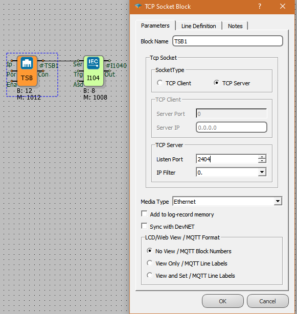
- By adding IEC104 slave block , IEC 104 will be activated on the RTU.
- TCP or Serialport block is connected to IEC104 block ser input.
- IEC 104 blocks must be added for each server to serve multiple servers.
- Asd input is used if IEC104 Asdu address is set from outside but not inside block.
- On the rising edge of the trigger, periodic transmission between IEC104 objects is activated and the selected objects are transmitted to the server periodically. Trigger input can be left blank.

Ser: TCP Socket Input. The TCP server socket block from which the IEC104 protocol will work is connected from this input
Trg: Trigger Input Trigger input for periodic sending. It works as a rising edge.
Asd: Asdu Address Input The ASDU address is used as input.
Q1: Link Status If the IEC104 connection between SCADA and RTU is installed, this output value is 1, otherwise 0.
Q2: SCADA write status, If SCADA requests select and execute, a pulse is generated at this output.
Custom Settings
- AsduAddress: IEC104 slave station ASDU address is defined
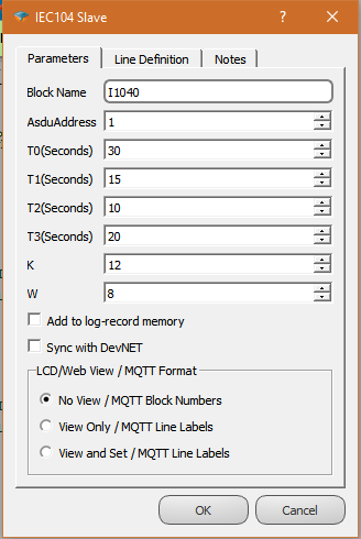
AsduAddress: IEC104 slave station ASDU address is defined
T0: Timeout for the establishment of the connection with the server. (Not used Slave)
T1: This parameter defines the time in seconds that slave waits maximum for an acknowledge from the master.
T2: Timeout period for Ack (A S-format frame will be sent at the latest after this time starting from the last received telegram from the master)
T3: Test frame sending time (A Test frame will be sent at the latest after this time starting from the last received telegram from the master)
K: The maximum allowable difference between the sequence number in the received packet and the number in the send status variable.
W: ACK(acknowledge message) sending frequency(sends ACK after W packets)
Sample Application
- In RTU logic projects , with the addition of IEC 104 Slave Block, the IEC 104 protocol is activated in the RTU. Variables in the RTU logic project, IEC104 association is provided in the variable address table.
Variable Mapping with Protocol
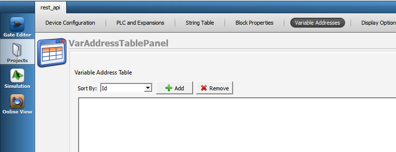
Variable Address Table
- The relevant protocol is activated in the RTU logic project by adding the protocol block. Variables in the RTU logic Project, association between protocol.is provided in te variable address table
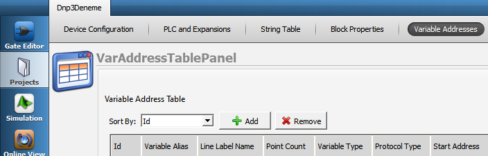
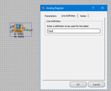
Defining Line Labels
*Line label can be defined for all blocks defined on the Mikrodiagram. In the variable table, the line label must be defined in order to be able to associate with the protocol addresses.
Attaching a Line Label
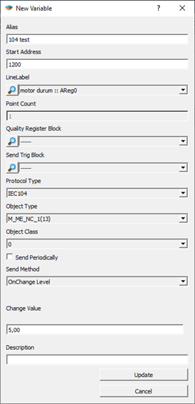
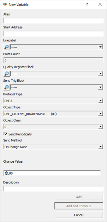
Alias: A special name is given that defines this defined variable.
Start Address: The address allocated for this variable on SCADA is written here. It is written as a decimal value
Line Label: The block to be associated on the Mikrodiagram is selected with the line label.
Point Count: Calculated automatically. It makes sense on tables.
Quality Register Block: Block entry to define Quality Register.
Send Trig Block: If you want to send IEC104 data with an independent trigger from the trigger input of the block, the trigger block is selected from this section and the periodic send option in the block special settings must not be ticked in order to send trigger-dependent data here.
Protocol Type: Modbus, Dnp3, IEC101, IEC104 are selected. Object type will change according to protocol type.
Object Type: IEC104 object type information selected. look the protocol type information for detailed information.
Object Class: The class information to which the variable belongs is selected.
Send On Trigger: IEC104 Slave block is the selection to send to this SCADA as a periodic send when the test is detected from the trigger input.
Send Method:
If the value of the defined variable is changed, the operation to be performed is selected.
Level: When the quantity defined in "Change Value" is changed, the transmission is triggered.
Percentage: The transmission is triggered when there is a change in the percentage defined in "Change Value".
None: Value exchange does not trigger posting
Change Value: With the "Send method", it adjusts the percentage change in the level.
Using DNP3 Slave
General Information
DNP3 protocol is a distributed communication protocol. Primary advantage are:
•Time-labeled variable support
•Ability to re-send the events that occurred during the absence of communication when connected with the time tags.
•The ability of SCADA to automatically send changes without the need to query.
•Ability to query multiple variables as a class, not individually
•Time syncronization
DNP3 SLAVE Driver
Mikrodev RTU devices are supports DNP3 SLAVE mode and gives service to DNP3 supported systems over TCP IP and/or SerialPort . The following services are supported:
1- Bulk object reading with Class object query
2- Time syncronization
3- Event control in instantaneous measurement data as a percentage and level
4- Automatic send the event datas
5- Periodically send the points of data
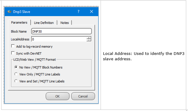
DNP3 Slave Block Definitions
Connections
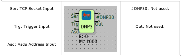
Connection Explanation
Ser: TCP Socket Input
The TCP server socket block, where the DNP3 protocol will run, is connected from this input.
Trg: Trigger Input
The trigger input for periodically send operation. Works as a rising edge.
Asd: Asdu Address Input
It is used as an ASDU address entry.
Block Explanation
By adding the DNP3 slave block, DNP3 is activated on the RTU. TCP or Seriport block is added to the DNP3 block Ser entry. To serve more than one server, a DNP3 block must be added for each server. If the DNP3 asdu address is to be set from outside the ASD entry is used.On the rising edge of trigger , periodic submission between DNP3 objects active selected objects, send to server with periodic COT. The input of trigger and can be left blank.
DNP3 Variable Table Definitions
Variable Table
To RTU logic project , Dnp3 becomes active in the DNP3 protocol within the RTU with the addition of the Slave Block to DNP3. Variables that in the RTU logic, The association of DNP3 is provided in the variable address table.
Line Label Definition
Line label can be defined for all blocks defined on the microdiagram. In order to associate with the protocol addresses in the variable table, the line label must be defined.
Line Label Attribution
Associating the protocol adresses with line labelss, The variable is provided from the menu by pressing the “Add” button in the address table.
● Alias:
A special name is given that defines this variable.
● Start Address:
The address reserved for this variable on SCADA is written here.İt is written as a Decimal value.
● LineLabel:
The block to be associated with on the microdiagram is selected by the line label.
● Point Coint:
It is calculated automatically. It makes sense in tables.
● Quality Register Block:
Block entry to define Quality Register.
● Send Trig Block:
If you want to send IEC104 data with an independent trigger from the trigger input of the block, the trigger block is selected from this section and the periodic send option in the block special settings must not be ticked in order to send trigger-dependent data here.
● Protocol Type:
Modbus, Dnp3, iec101, iec104 to choosing from among them. The Object Type will change according to the protocol type.
● Object Type:
DNP3 object type information is selected. See protocol type information for detailed information.
● Object Class:
The class information to which the variable belongs is selected.
● Send On Trigger:
When Dnp3 Slave is detected from the trigger input in the trigger block, it is the choice of whether to send this variable as a periodic send to SCADA.
● Send Method:
When the value of the defined variable changes, the operation to be performed is selected.
None: Spinner does not trigger submission.
Level: When the amount defined "Change Value" changes, sending is triggered.
Percentage: Submission is triggered when there is a percentage change defined in " Change Value”.
● Change Value:
Sets the percent or level change value with” Send method".
DNP3 Object Types
DNP3 Object Types in Reading Direction
| DNP3 Object Type | Register Data Type |
|---|---|
| Single Bit Binary Input : Data Object 01 - Variation 01 | Binary, Word, Analog, Long |
| Binary Input With Status :Data Object 01 - Variation 02 | Binary, Word, Analog, Long |
| Binary Input Change Without Time : Data Object 02 - Variation 01 | Binary, Word, Analog, Long |
| Binary Output : Data object 10 - Variation 01 | Binary, Word, Analog, Long |
| Binary Output Status : Data object 10 - Variation 02 | Binary, Word, Analog, Long |
| 32 BIT Analog Input : Data Object 30 - Variation 01 | Long |
| 16 BIT Analog Input : Data Object 30 - Variation 02 | Binary, Word |
| 32 BIT Analog Input Without Flag : Data Object 30 - Variation 03 | Long |
| 16 BIT Analog Input Without Flag : Data Object 30 - Variation 04 | Binary, Word |
| Short Float Analog Input Without Flag : Data Object 30 - Variation 05 | Analog |
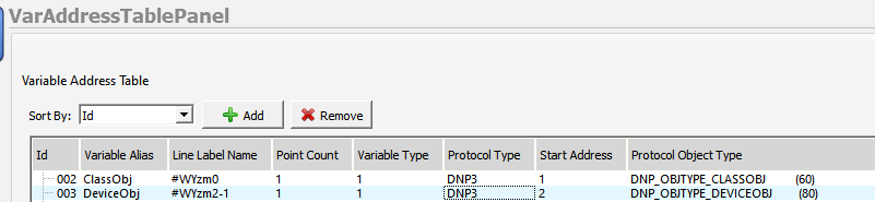
NOTE 1: A variable of type DNP_OBJTYPE_CLASSOBJ must be added from the variable Adress table to draw Class 0, Class 1, and Class 2 data. Other settings of this variable, such as address, line tag, can be selected at random.
DNP3 Object Types in Control Direction
The write variable is also automatically generated for each block mapped to the read type. The types of variables that can be accessed as write to defined read objects are as follows:
| DNP3 Object Type | Register Data Type |
|---|---|
| Control Relay Output Block : Data Object 12 - Variation 01 | Binary, Word, Analog, Long |
| 32 Bit Analog Output Block : Data Object 41 - Variation 01 | Long |
| 16 Bit Analog Output Block : Data Object 41 - Variation 02 | Binary, Word |
| Short Float Analog Output Block : Data Object 41 - Variation 03 | Analog |
DNP3 Event Mechanism
Event Definition for DNP3 Objects
In the variable address table, the send in change selection is available for DNP3 objects. When the value of the variable defined in this menu changes, the operation to be performed is selected.
● None: Spinner does not trigger submission
● Level: when the amount defined in “Change Value” is changed, the sending is triggered.
● Percentage: Submission is triggered when there is a percentage change defined in " Change Value”.
The change face or level is set with the value” Change Value". Sets the percent or level change value with “Send method”.
DNP3 Instantaneous Transmission of Event Situations
The RTU device tags the states defined as send and change detected as events and assigns a time tag to the event. In case of a tagged event, if there is a connection to the server and the server is active in the device sending “UNSOLICED”, the relevant object is immediately forwarded as “UNSOLICED”.
If the connection exists with the server and the events detected with the “UNSOLICITED” sending active are sent with the DNP3 object types specified in the following table.
| DNP3 Object Type | Register Data Type |
|---|---|
| Binary Input Change Without Time : Data Object 02 - Variation 01 | Binary |
| 32 Bit Analog Input Change Without Time : Data Object 32 - Variation 01 | Long |
| 16 Bit Analog Input Change Without Time : Data Object 32 - Variation 02 | Word |
| Short Float Analog Input Change Without Time : Data Object 32 - Variation 05 | Analog |
DNP3 Time-Tagged Submission Of Event States
Event Controls continue passively sending “UNSOLICED” even if there is connection to the server or even if there is no connection. In the event of an event under these circumstances, event information is recorded in the event memory with the time tag and this data is kept in the device as CLASS 1 data.
This event data stored in memory can be read by the server with Class 1 data read management. This CLASS 1 data is also automatically forwarded to the server by RTU if” UNSOLICED " sending is enabled.
Class 1 event data is dispatched with the DNP3 object types specified in the following table.
| DNP3 Object Type | Register Data Type |
|---|---|
| Binary Input Change With Time : Data Object 02 - Variation 02 | Binary |
| 32 Bit Analog Input Change With Time : Data Object 32 - Variation 03 | Long |
| 16 Bit Analog Input Change With Time : Data Object 32 - Variation 04 | Word |
| Short Float Analog Input Change With Time : Data Object 32 - Variation 07 | Analog |
Using MQTT
General Information
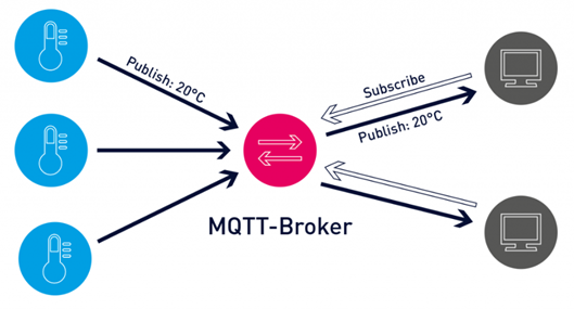
MQTT (Message Queuing Telemetry Transport) protocol is a machine-to-machine (M2M) message-based protocol widely used on the Internet. It has been adopted in the Internet of Things (IoT) ecosystem with its light weight and low resource consumption. Almost all IoT cloud platforms support MQTT protocol to send and receive data from smart objects.
Block Definitions
MQTT Config Block
To configure MQTT settings, you must first add the Mqtt Config block to your project.

Pin Definitions;
• Soc: It is used for TCP socket block connection. Mqtt Config block cannot be used without TCP socket block.
• Trg: When periodic data transfer is desired, a trigger should be given to the mqtt config block from this input. If this entry is left blank, data is transmitted according to other specified conditions.
• Mqtt0: Output showing the connection status. The information from this output is as follows;
      - 0: TCP Disconnected
      - 1: TCP Connecting
      - 2: MQTT Connecting
      - 3: MQTT Connected
• Sta: Output showing the communication status. The information from this output means:
      - 0: MQTT Send Conn Pack
      - 1: MQTT Idle Status
      - 2: MQTT Subscribe Status
      - 3: MQTT Publish Status
• Pub: Output showing Publish timeout.
Mqtt Config Block Custom Settings;
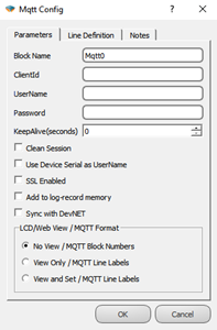
Definitions;
• Client Id: The field where the device is manually given an ID for the broker connection.
• User Name: The field where the device is named for the broker connection.
• Password: Password field entered in the device for the broker connection.
• Keep Alive: If the connection between the broker and the Publisher is lost, the waiting time before reconnecting.
• Clean Session: If selected, messages will be broadcast if there is communication between the device and the broker, otherwise the information recorded in communication interruptions will not be sent.
• Use Device Serial as User Name: If selected, the serial number of the device is used as the device username.
• SSL Enabled: It is marked to make the connection with SSL. (Only active in DM Series.)
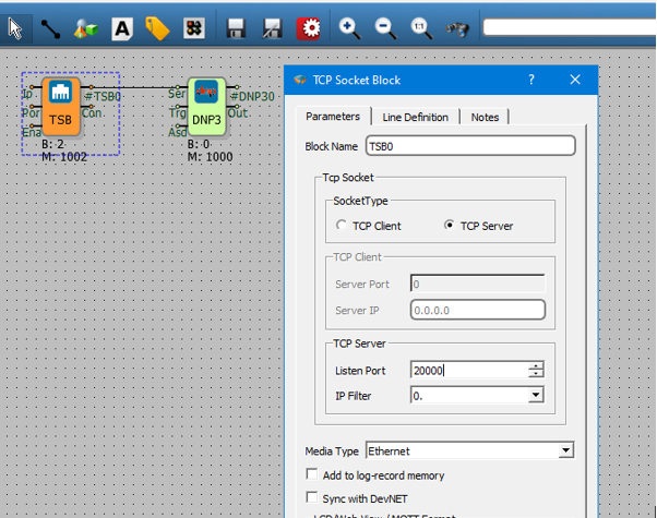
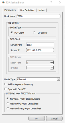
TCP Socket Block Connection
The output of the TCP Socket block is connected to the Soc input of the Mqtt Config block.

The special settings of the TCP Socket block should be made for mqtt connection as follows;
• TCP Client should be selected as the socket type,
• The mqtt server IP to be connected to the Server IP section must be entered,
• Mqtt server port information should be entered in the Server Port Section,
• As for the media type, Ethernet, GSM or WI-FI can be selected according to the characteristics of the microdev device used.
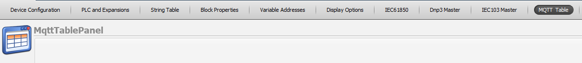
MQTT Table
The table where all MQTT-related adjustments are made can be accessed from the Projects/MQTT Table tab.
Topics The Publish
In this table, the Publish topic is entered to publish the data to the broker. The topic name is entered on the screen that appears by pressing the Add Topic button in the table. Block definitions where you can enable/disable Qos, Retain, Last Will, Payload settings, send on exchange and periodically send options are also made on this page.
Definitions;
• Topic Name: The field where the topics you will send the messages are determined.
• QoS: Quality of Service refers to the agreement between the sender of a message and the receiver of the message. The QoS levels are as follows;
o QoS 0: Minimum data transfer is ensured. At this level, each message is forwarded to a subscriber and no confirmation is received that the message has arrived.
o QoS 1: The broker tries to transmit the message and waits for an acknowledgment response from the subscriber, if no confirmation is received within a specified time frame, the message is sent again.
o QoS 2: The broker receives two acknowledgments to ensure that the subscriber receives the message and only once.
• Retain: If this option is checked, if the connection between the broker and the subscriber is broken, the last value will be saved in memory.
• Is Last Will Topic: Last will topic. If a topic is created and this option is checked, the message under this topic will be forwarded to the subscribers when the device is disconnected from the broker.
• Payload Type: It is determined in which format the message content will be sent. Subscriber interprets incoming messages with this information. “MJson v1” can be selected if a time stamp is desired to be added to the sent messages.
• On Change Send Enable Block: Block selection added in the diagram to enable or disable the sending feature of the created topic on change.
• Periodic Send Enable Block: Block selection added in the diagram to enable or disable the periodic sending feature of the created topic.
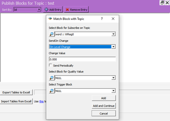
Publish Blocks for Topic
In this table, the blocks to be published for the relevant Topic are selected. After clicking the topic in the Publish to topic table, the Add Entry button becomes active and by pressing this button, the block to be published in the project is selected. How to transmit the data can also be selected from the screen.
Definitions;
• Select Block for Subscribe on Topic: The area where the block that you want to send as a message in your project is selected.
• Send On Change: Send selection field on exchange
o On Level Change: Send when there is a change in the value specified in Change Value, if 0 is written, it will be sent in every change.

o On Percent Change: Send when there is a percentage change of value specified in Change Value, for example 10%.
• Change Value: Change amount input field.
• Send Periodcally: If checked, a message is sent every time a trigger comes to the trg input of the mqtt config block.
• Select Block for Quality Value: The block in which the Quality value included in the message content is selected in MJson v1 payload type.
• Select Trigger Block: Apart from change or periodicity, we can send the message by triggering the block we will specify here.
Note: Blocks used in messages; It can be sent and received with the block number (B:3006) under the block, or it can be added to the messages with line tags (word_publish_ch). This selection is made under the Mqtt Format tab in the block properties.
• Message that will appear if View and Set is selected;
![]()
• The message that will appear if No View is selected;
![]()
Subscribe to Topic
In this table, the relevant subscribe topic is entered to send data from the broker to the device.
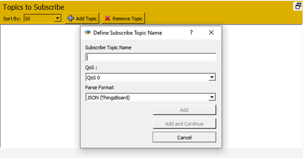
Definitions;
• Subscribe Topic Name: Enter the name of the topic to be subscribed to.
• QoS: Service quality level is selected.
• Parse Format: Select the format in which the messages will be parsed.
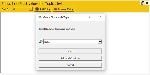
Subscribed Block Values for Topic
From this screen, the blocks to be associated for the subscribe topic are added. To use line tags, mqtt format should be selected as view and set from the special settings of the relevant block.
Special Applications
Ubidots
When you want to use Mikrodev PLC with ubidots mqtt, the following steps should be followed in addition to the settings described above;
From the Mqtt Config block custom settings, Ubidots ID should be entered in the Client Id section and the Token Key of the device created in Ubidots should be entered in the Username section.
Publish Topic: Enter as /v1.6/devices/< Device Name >. There is no need to define variables in the ubidots calculation for the blocks to be associated. With the first sent data, the variables are created automatically by Ubidots. The data is read on the Ubidots server with the block number or line tag.
Subscribe Topic: Entered as /v1.6/devices/< Device Name >/< Value Name >. A separate connection must be defined for each data to be subscribed. Data must be defined in the Ubidots environment. If the line tag is to be used, the variable created in Ubidots should have the same name as the line tag, if the line tag is to be transmitted only with the block number, the variable with the same name as the block number should be defined in the ubidots environment.
Example Applications
Topic Publish
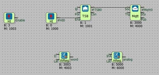
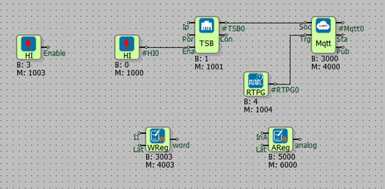
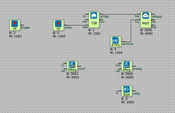
General Configuration; After the project is created, the diagram is designed as in the figure, the mqtt formats of word and analog registers are selected as view and set.
Send On Change;
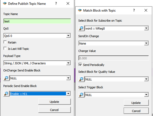
Follow Projects > MQTT Table >Topics to Publish > Add Topic.
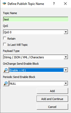
Select the Topic name, enter the High gate we have prepared in the diagram for the OnChange Send Enable Block, and click add.
Then, from the Publish Blocks for Topic section in a subtable, click to the Add Entry.
Select the block in the diagram that you want to broadcast as a message to the Select Block for Subscribe on Topic section. In the SendOn Change section, On Level Change is selected and Change Value is set to 0 so that it can send a message every time the value changes. Click on Add and continue.
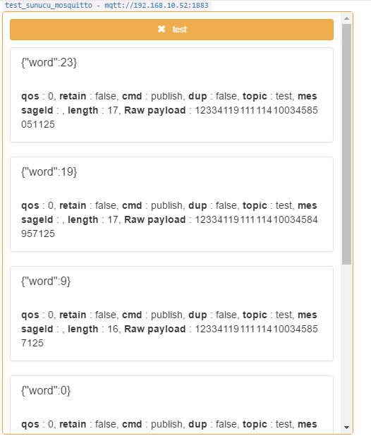
The project is loaded on the device and online monitoring is opened.
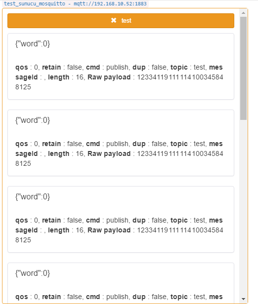
Subscribe to the topic opened with a program such as MQTTBox. After watching the mqtt config block value of 3 in online monitoring in the Mikrodiagram, when the value of the register is changed, it is seen that the value is published.
Periodic Send; In addition to the configuration sent in the change, a real time pulse generator is added to the trg input of the mqtt config block,
Real time pulse generator is set for 5 seconds to broadcast a message periodically every 5 seconds and the created topic is changed as follows. OnChange Enable Block= NULL and Set the High gate in the Periodic Send Enable Block diagram, In the Select Block for Subscribe on Topic section, select SendOn Change= None and click Send Periodically.
The project is loaded back to the device and incoming messages are observed.
Subscribe Topic
General Configuration;
After the project is created, the diagram is designed as in the figure, the mqtt formats of the word and analog registers and the relay output are selected as view and set.
Follow Projects > MQTT Table >Topics to Subscribe > Add Topic.
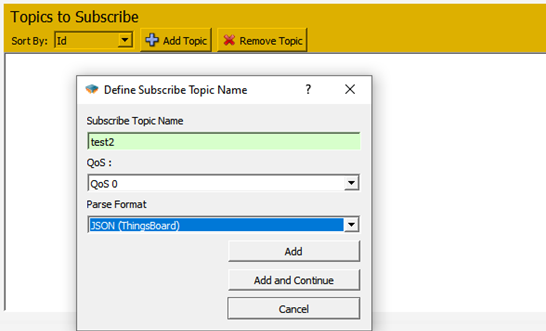
Enter the topic name and click Add. Then, the add entry is clicked from the Publish Blocks for Topic section in a subtable.
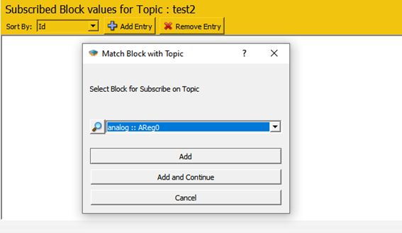
Here, the block to which the subscribed value will be transferred is selected.

After all blocks to be subscribed are determined, the project is loaded into the device.
![]()
When the message is published to the test2 topic with the above format, the final state of the variables is as follows;

Using MOD-C
Serial Port Block Definitions
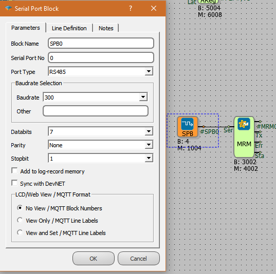
Note: for RS485; Serial Port No: 0 , for RS232; Serial Port No: 1
Note: We can leave the values in this section as default.
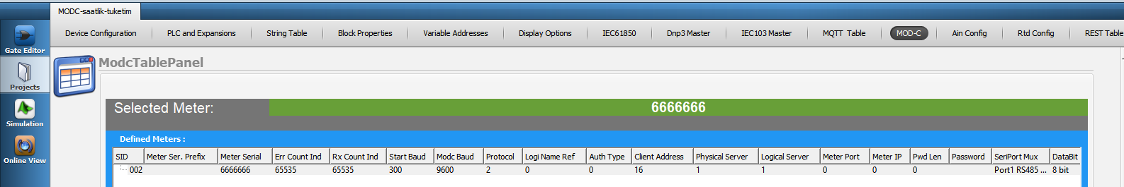
MOD-C Table Panel
Add Meter
Adding Meter, adding OBIS Code, adding programming mode command are done in this section.
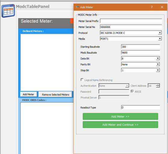
Note: For Makel Meter ; Meter Serial Prefix: MSY
Note: If the serial number is less than 8 digits, it is necessary to complete the serial number to 8 digits. For this, it is necessary to write 0 in the counter serial prefix section until the number of missing digits.
Note: Port 1 : RS485 , Port 2 : RS232 , Protocol : Mode C
| Meter | Makel | Köhler | EMH |
|---|---|---|---|
| Starting Baudrate | 300 | 300 | 19200 |
| MODC Baudrate | 9600 | 9600 | 19200 |
| Data Bit | 7 | 7 | 7 |
| Parity Bit | Even Parity | Even Parity | Even Parity |
| Stop Bit | 1 | 1 | 1 |
| Readout Type | 0 | 0 | 0 |
Add OBIS Codes
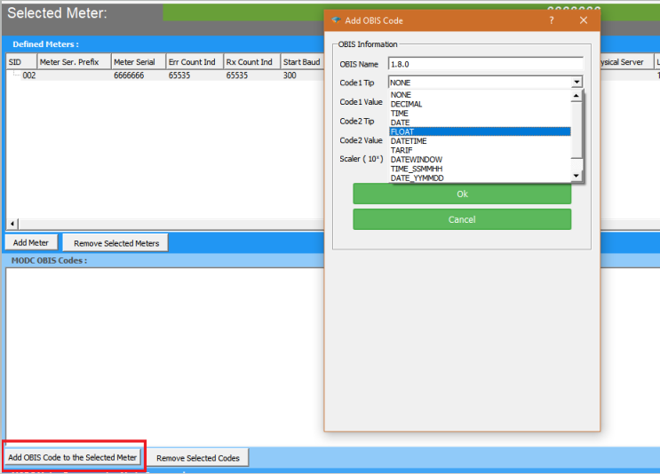
Add Programming Mode
Reading OBIS Codes Outside The Service List
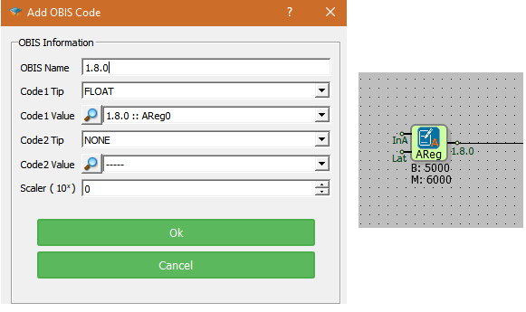
First of all, we enter the meter number we want to read and the OBIS codes we want to read on it.
We enter the OBIS codes, outside the service list.
For example; 2.8.0 Obis code.
Add Programming Mode Command to the Selected Meter.
We enter the code we want to read.
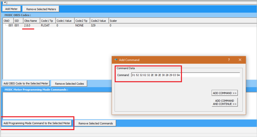
Note: An example is given for the Köhler brand meter. You can request the codes suitable for your device from your meter manufacturer.
Load Profile Reading
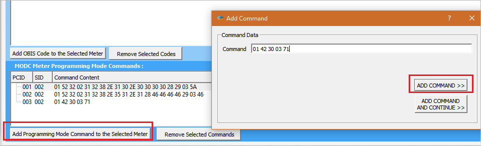
Choose the Meter.
Add Programming Mode Command to the Selected Meter
We add the commands one after the other.
01 52 32 02 31 32 38 2e 31 30 2e 30 30 30 30 28 29 03 5a  // [ Read Load Profile Index Information ]
01 52 32 02 31 32 38 2e 35 31 2e 31 28 46 46 46 46 29 03 46 // [ Read values defined in load profile MODC OBIS Codes section ]
01 42 30 03 71  // [ Ends the load profile reading process ]
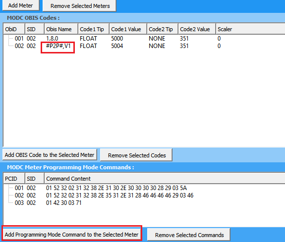
- We add the data we want to see the load profile values, from the Add OBIS Code to the Selected Meter.
Load Profile Codes:
for Ael tf 19/20/21 ;
#P1#,2,0,8,0; ----> Load Profile Index Value (DECIMAL)
#P1#,2,20,8,-3; ----> +T value (FLOAT)
#P1#,2,28,8,-3; ----> -T value (FLOAT)
#P1#,2,36,8,-3; ----> +Ri value (FLOAT)
#P1#,2,44,8,-3; ----> +Rc value (FLOAT)
#P1#,2,52,8,-3; ----> -Ri value (FLOAT)
#P1#,2,60,8,-3; ----> -Rc value (FLOAT)
#P1#,2,8,10,0; ----> Load profile record date epoch (DATETIME)
for Makel c410, c500 ;
#P2#,Active ----> +T value ( FLOAT )
#P2#,Capacitive  ----> +Rc value  ( FLOAT )
#P2#,DateTime ----> Load profile record date epoch   (DATETIME)
#P2#,I1 ----> IrmsA value  ( FLOAT )
#P2#,I2 ----> IrmsB value ( FLOAT )
#P2#,I3 ----> IrmsC value ( FLOAT )
#P2#,Inductive  ----> +Ri value   ( FLOAT)
#P2#,V1 ----> VrmsA value ( FLOAT )
#P2#,V2 ----> VrmsB value ( FLOAT )
#P2#,V3 ----> VrmsC value ( FLOAT )
Rest API Configuration
Defining REST API servers
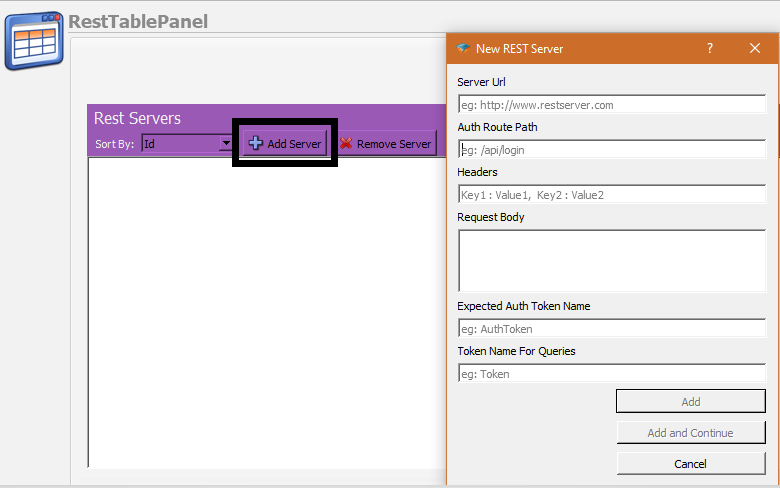
The first thing to do is to define some parameters related with the REST API Server. On the RestTablePanel, click on Add Server button to open New Rest Server Dialog. On the dialog you will be asked the following parameters:
Server URL
The root url of the server which serves the API.
Auth Route Path
If the API requires authentication, set the path for the authentication path here. Do not use the root url here, only the relative path should be inserted(eg : /api/login ) .
Headers
If you need to use any special headers during authentication process insert them in a comma separated key/value format(eg: Key1 : Value1, Key2 : Value2) .
Request Body
If you need to use a request body during authentication process insert it here.
Expected Auth Token Name
After authentication, if the server sends a token for authentication , insert the name used for token data in here.
Token Name For Queries
After you get the token data, you may need to use a different token name on your API calls. Write here the token key name to be used.
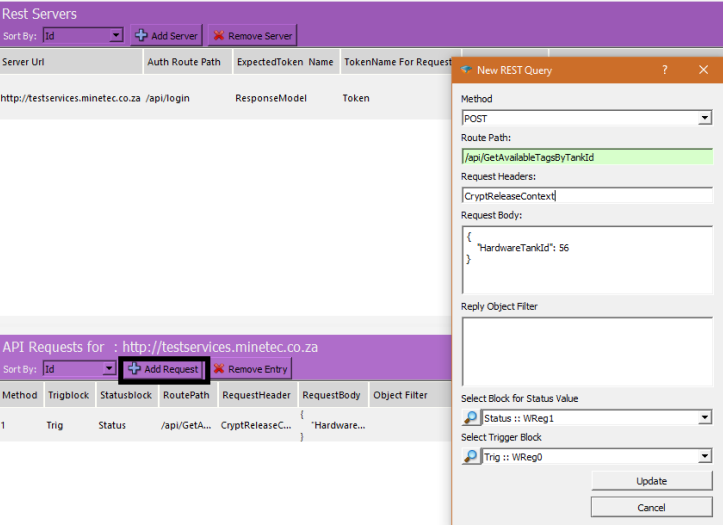
Add new REST Request Object
After you add a Rest Server, now you can start to add API request definitions on that server. Click on the Rest Server to which you will add the request and click Add Request button. You need to insert the following parameters on the dialog
Method
The HTTP method to be used for the request. It could be a POST, GET, PUT or DELETE request.
Route Path
The route path of the request. Start with "/" and do not use the root URL here (eg: /api/GetTankLevel ).
Request Body
If you need to use a request body during the API call insert it here.
Reply Object Filter
After you send the API request the server will send you a reply in JSON form. You need to use a filter to be able to get the relevant data from this JSON object. Please see the following example to be able to get the data in different forms:
The example reply from the server is:
  {
    "Message": null,
    "ResponseModel": {
        "AvailableTags": [
            {
                "CanTakeFuelOutside": false,
                "CurrentMachineHours": 20,
                "THPT": 85,
                "TagNumber": "TestTag000000001",
                "UnitType": "Hour",
                "VehicleTankCapacity": 300
            },
            {
                "CanTakeFuelOutside": false,
                "CurrentMachineHours": 102,
                "THPT": 85,
                "TagNumber": "TestTag000000002",
                "UnitType": "Hour",
                "VehicleTankCapacity": 300
            }
        ],
        "ServerDateTime": "14.02.2021 22:01:44"
    },
    "Type": "S"
}
Example Filters
• To be able to get the VehicleTankCapacity of the first element of the AvailableTags array and write it into a block with number 6000 :
ResponseModel.AvailableTags[0].VehicleTankCapacity ,6000;
• Get all the CurrentMachineHours in the AvailableTags array and write them into a table block with number 6000:
ResponseModel.AvailableTags[].CurrentMachineHours , 6000;
• Find the object with TagNumber is equal to "TestTag000000002" in the array and get the VehicleTankCapacity value of this object and write that value into the block with block number 6000:
ResponseModel.AvailableTags[].TagNumber(TestTag000000002).VehicleTankCapacity, 6000;
Select Block for Status Value
The return code of the API request will be written into this block
Select Trigger Block
Whenever this block is enabled the API request will be sent to server.
Telediagram License
Installing the License File
To get a valid license please send your "hardware id" to [email protected].
To find out your hardware id; after you download and install Telediagram application, go to the "bin" directory of the application and run "license_user.exe" .
Before running "license_user.exe" make sure that no "usb stick" or "external harddrive" is connected on your computer since that may change your hardware ID.
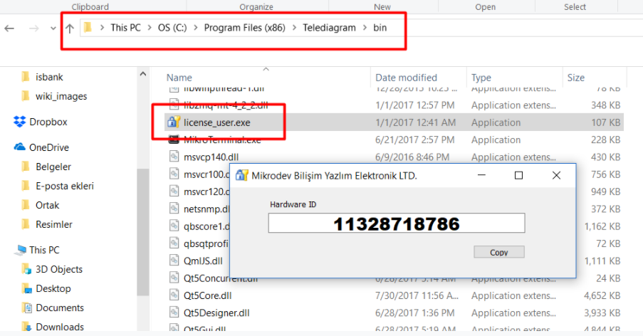
After you receive a valid "tlicense.dat" file, copy this file into the "bin" directory of Telediagram application
The licence will automatically be loaded when you restart the Editor