Example Projects
Basic Logic Examples
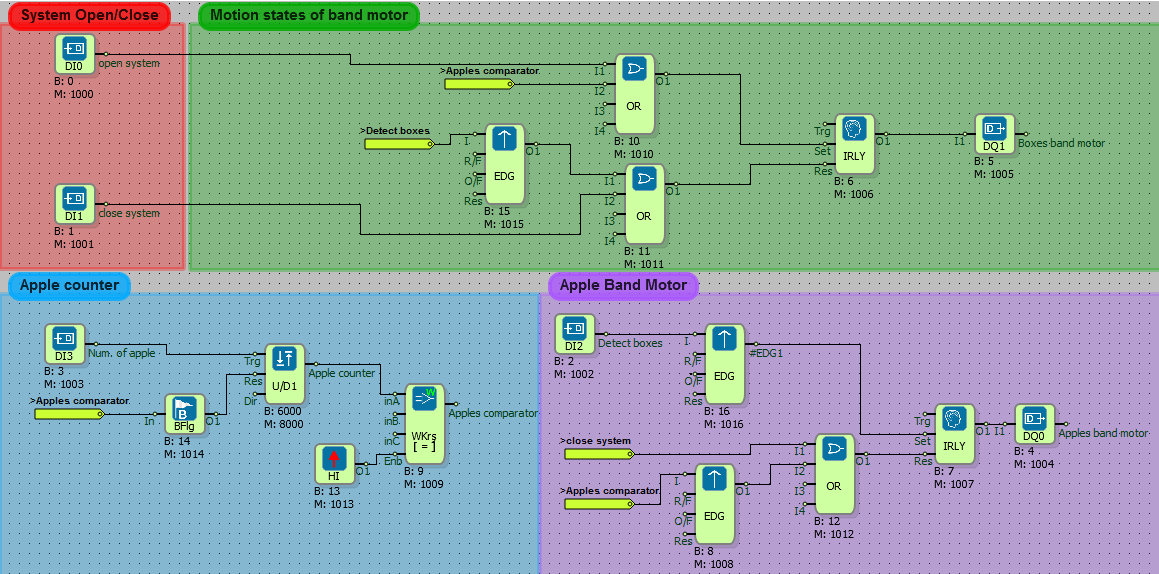
Apple Boxing Automation
What You Need to Know Before Design
- DIGITAL INPUT
- DIGITAL OUTPUT
- BINARY FLAG
- OR
- AND
- EDGE
- IMPULSE RELAY
- HIGH
- UP / DOWN COUNTER
- WORD COMPARATOR
- Adding a Line Label
Diagram Algorithm
In apple automation, apples coming from apple conveyor band will be counted and 20 pieces will be passed into the box. When the number of apples counted is 20, the conveyor carrying the boxes will move. For this, the belt motor in which the boxes come will be controlled
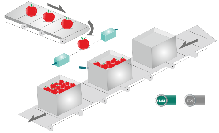
Diagram Solution
- The apple counting and box detection sensor generating the digital output is connected to the digital inputs of the PLC device.
- The box band motor will be activated with DQ1 when the system is first turned on or when the apple comparator generates a high level signal.
- When the box is detected, the box conveyor motor will be stopped and the apple conveyor motor will be activated immediately to send the apples.
- When the apple counting process is completed, the conveyor motor will reactivate and the cyclic process will continue.
- The box conveyor and the apple conveyor motors are stopped when the system shut off button is pressed.
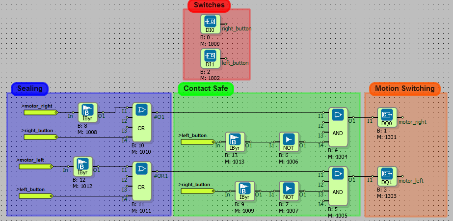
Sealing and ContactSafe Motor Switching
What You Need to Know Before Design
- DIGITAL INPUT
- DIGITAL OUTPUT
- BINARY FLAG
- AND
- NOT
- OR
- Adding a Line Label
Diagram Algorithm
- When the button is pressed forward, the motor will start to move forward and the button will continue even if it is not pressed forward.
- When the button is pressed back the engine will stop and immediately the engine will start to run in reverse direction.
- If two buttons are pressed at the same time, the system will stop.
Diagram Solution
- In the sealing algorithm, the 'motor forward' will start to work when the high signal is applied via 'forward button'. The 'motor forward' label will produce a high level output when the 'motor forward' starts to work and the 'motor forward' will be active even if the button is not pressed.
- In the safety algorithm, the two buttons pressed together condition is checked. Binary flag is used to generate a 1 cycle delay in button controls.
- In the above picture there is an online monitoring screen image where the button is pressed forward, the motor is forward activated and the 2 buttons in the picture below are pressed together so that the motor's forward and reverse outputs are inactive.
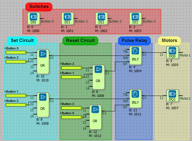
Controlling Two Motors With Four Buttons
What You Need to Know Before Design
- DIGITAL INPUT
- DIGITAL OUTPUT
- OR
- IMPULSE RELAY
- Adding a Line Label
Diagram Algorithm
- When Button 0 is pressed, Motor 1 will started.
- When Button 1 is pressed Motor 2 will started.
- When Button 2 is pressed, two motors will start together
- When Button 3 is pressed, two motors will stop together.
- If the start button of Motor 2 is pressed while Motor 1 is running, Motor 1 will stop and Motor 2 will start to work.
Diagram Solution
- In the set algorithm, the running states of the motors; in the reset algorithm, the stopping states of the motors and in the pulse impulse part the permanence of the active or passive states of the motors are provided.
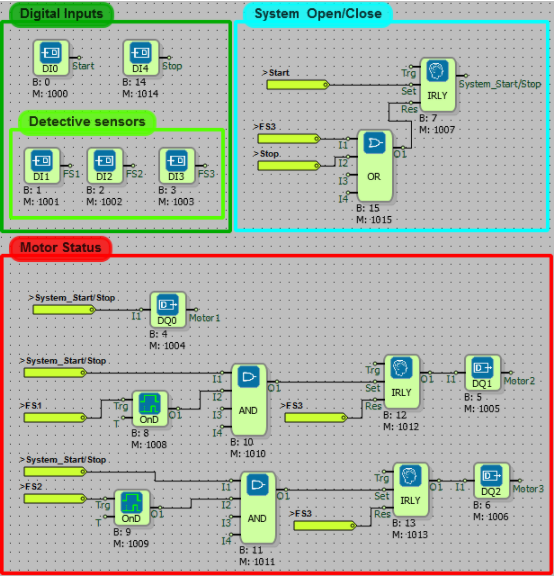
Conveyor Automation
What You Need to Know Before Design
- DIGITAL INPUT
- DIGITAL OUTPUT
- AND
- OR
- IMPULSE RELAY
- ON DELAY
- Adding a Line Label
Diagram Algorithm
- When the Start button is pressed, the Motor 1 will start immediately.
- The program will stop immediately when any Stop button is pressed.
- Motor 2 will run, when FS1 has detected the object after 2 seconds.
- Motor 3 will run, when FS2 has detected the object after 3 seconds.
- When the FS3 detects the object, the program will stop immediately.
Diagram Solution
- The system on-off function was implemented using the pulse relay. When the system is off, the system will be turned on when a high level signal is received from the Start / Stop button, and the system will shut down when a high level signal is received while the system is on.
- When the system is first turned on, motor1 will start to operate with the label 'System Start / stop' pulse relay.
- When the FS1 sensor activates, it will wait for 2 seconds and then work. For this algorithm, the FS1 tag was checked with an on delay.
- When the FS2 sensor is activated, motor 3 will start after waiting for 3 seconds with delay.
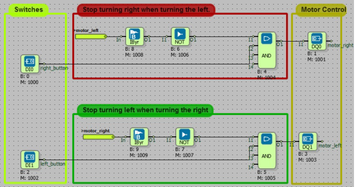
Contact Locking Motor Control
What You Need to Know Before Design
- DIGITAL INPUT
- DIGITAL OUTPUT
- BINARY FLAG
- AND
- NOT
- Adding a Line Label
Diagram Algorithm
- Motor right and left turn conditions will be checked.
- If the motor turns to the left, it will not turn to the right, if it turns to the right, it will not turn to the left.
- If you press left while turning to the right, it will continue to turn to the right, it will be the same in the left turning situation.
- If neither of the buttons is pressed, the motor will not function.
Diagram Solution
- Turn left turn to the right: If the motor is turning to the left, a low signal will be sent to the AND block because that the 'motor left' tag is high and not for the receipt. Therefore, if the left movement of the motor is active, it will not turn to the right even if the right button is pressed. The controller has a cycle delay using binary flags so that it does not enter the endless loop.
- The same situation in the upper part is also used to prevent turning to the left when turning to the right.
- It is observed that there is no button pressed in the online monitoring screen above.
- In the following example, the right turn of the motor is observed when DI0 is active.
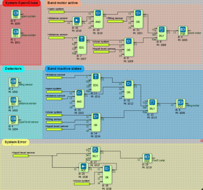
Bottle Liquid Level Control
What You Need to Know Before Design
- DIGITAL INPUT
- DIGITAL OUTPUT
- BINARY FLAG
- AND
- OR
- NOT
- IMPULSE RELAY
- EDGE
- Adding a Line Label
Diagram Algorithm
- The bottles pass through the conveyor belt in groups of three. When the sensors can not see each other, the filling valves open to allow the bottles to start filling. In the meantime, the distance sensors next to the fill valves begin to measure. It is filled until the desired distance is reached. Then the filling valves are closed. The conveyor belt starts to move again and the other bottle is expected to be detected.
Diagram Solution
- When the system is first turned on, the band motor is running. When the sensors detect the bottles, the logic is high and bottles are expected to be filled by stopping the motor. After the bottles are filled, the conveyor belt motor is energized again and the bottles are kept on the conveyor belt. The liquid level control sensors placed at the end of the belt control the filling bottles. If the liquid level in the bottle is not at the desired reference point, the system is stopped and the fault lamp is lit. The fluid level sensor is logic high when there is no desired reference value.
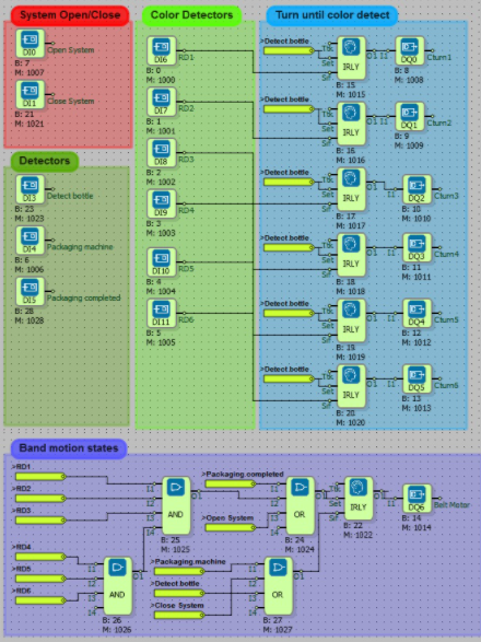
Bottle Packing Automation
What You Need to Know Before Design
- DIGITAL INPUT
- DIGITAL OUTPUT
- AND
- OR
- IMPULSE RELAY
- Adding a Line Label
Diagram Algorithm
- The bottles pass through a conveyor belt in groups of three. When the tips of the sensors can not see each other, the filling valves open to allow the bottles to start filling. In the meantime, the distance sensors next to the filling valves start measuring. The distance is filled until the level is increased to the desired level. When the sensor reaches the specified level, the filling valves are closed. The conveyor belt moves and waits to detect the other bottle.
Diagram Solution
- When the system is first turned on, the band motor is running.
- When the sensors sense the bottles, the logic is high (1) and bottles are expected to be filled by stopping the belt motor.
- After the bottles are filled, the conveyor belt motor is energized again and the bottles are kept on the conveyor belt.
- The liquid level control sensors placed at the end of the conveyor belt control the filling bottles.If the liquid level in the bottle is not at the desired reference point, the system is stopped and the fault lamp is lit. If the fluid level sensor is not the desired reference value, the logic is high (1).
- RD is the abbreviation of color detection, while Cturn is the abbreviation of rotation until color is perceived.
Led SwitchOn Delay With Functional Button
What You Need to Know Before Design
- DIGITAL INPUT
- AND
- NOT
- OR
- IMPULSE RELAY
- DIGITAL OUTPUT
- Adding a Line Label
Diagram Algorithm
- When the two buttons are pressed at the same time, the first lamp lights up.
- When three buttons are pressed in the system with three buttons in total, the second lamp lights up and the motor enters the circuit.
- The system can also be shut down with the Stop button.
Diagram Solution
- When Button_A and Button_B are pressed at the same time, the Lamp 1 lights up.
- When Button_A, Button_B and Button_C are pressed at the same time, the Lamp 2 lights up.
- When the Lamp 2 comes on, the Motor starts to work.
- A Stop Button has been added to stop the entire system.
Bottle Recognition And Filling Automation
What You Need to Know Before Design
- DIGITAL INPUT
- AND
- OR
- IMPULSE RELAY
- EDGE
- DIGITAL OUTPUT
- NOT
- TIMER OUTPUT RELAY
- BINARY FLAG
- Adding a Line Label
Diagram Algorithm
- Robust bottles will be filled for three seconds.
- Robust and broken bottles are determined with the camera.
- Broken bottles are thrown out with the cylinder.
- The camera will work immediately after the sensor detects the bottle.
Diagram Solution
- With the Start button, the system starts and the belt starts moving.
- The camera works when the bottle sensor is activated while the belt is moving.
- The information that the bottles are firm or broken is sent to the system.
- The belt stops when you reach the bottle filling point.
- If the bottle is broken, the piston will run and the bottle will be ejected from the belt. If it is intact, the valve will be opened and the filling process will be done within the time specified by the timer.
- After filling, the belt becomes active.
- These operations continue until the stop button is pressed.
Start and Resume Motor
What You Need to Know Before Design
- DIGITAL INPUT
- DIGITAL OUTPUT
- SYMETRIC PULSE GENERATOR
- TIMER OUTPUT RELAY
- EDGE
- IMPULSE RELAY
- BINARY FLAG
- OR
- Adding a Line Label
Diagram Algorithm
- After the motor connected to the output DO0 has been running for 5 seconds, the lamp connected to the output DO1 will flash for 0.5 seconds at intervals of 10 seconds.
- These operations will start when the button connected to the input DI0 is pressed, and will be stopped with the button connected to the input DI1.
Diagram Solution
- When the start button is pressed, the engine is on for 5 seconds.
- When the engine stops, the lamp is triggered by the edge gate and flashes at 0.5 second intervals for 10 seconds.
- After 10 seconds the engine restarts.
- The system repeats this way.
- When the Stop button is pressed, the entire system stops.
Systematic Motor Operation
What You Need to Know Before Design
- DIGITAL INPUT
- EDGE
- LOW
- DIGITAL OUTPUT
- Adding a Line Label
Diagram Algorithm
- The system will be controlled by the limit switch, start and stop buttons.
- When the Start button is pressed, Motor 1 will start to operate.
- When a mechanical system comes into contact with the limit switch, the Motor 1 will remain active as long as the Motor 2 applies pressure to the moving system limit switch.
- After the mechanical system passes the limit switch, the Motor 1 will continue to run until the Motor 2 stops.
- All systems will stop when the Stop Button is pressed.
- When the Start Button is pressed again to restart the stopped system with the Stop Button, the motors will continue to operate in that position.
Diagram Solution
- This system will be controlled by the limit switch and stop button.
- The mechanical system will start the Motor 1 when it contacts the limit switch until the stop button is pressed. The Motor 2 will run as long as the limit switch is pressed.
- Stop button will stop the entire system.
Lift Automation
What You Need to Know Before Design
- DIGITAL INPUT
- Adding a Line Label
- AND
- DIGITAL OUTPUT
- NOT
- TIMER OUTPUT RELAY
- ANALOG FLAG
Diagram Algorithm
- The project will be prepared for a three-storey elevator. The controls that need to be done in elevator control are listed as follows.
- The elevator cab is raised / lowered by moving the motor forward and backward. Motors like cylinders continue turning for a while after the power is turned off. In this case, the elevator cab will not stop at the exact desired location, so the elevator will have a braking system.
- Only the motor and elevator car lighting will be checked from the digital outputs.
- There are 3 floor buttons and 1 emergency stop button in the cabin.
- Each floor has an elevator call button.
- There are sensors on each floor to understand which floor of the elevator car is the floor.
- If the elevator door is opened or the elevator call button is pressed while on the ground, the cabin lighting and the busy lamp are lit for 10 seconds.
- In case of emergency, the stop button will be provided to keep the cabin in place.
- An audible alarm or an alarm button must be placed in the cabin to be notified of any malfunction.
- In the designed system, the elevator door will be opened and closed by hand (a system with automatic opening motor is required). Telephone voice notification will be made independent of the PLC. The elevator door will not open unless the cab is on the floor.
Diagram Solution
- 3-storey elevator system to be controlled in this system.
- Motor forward output will move the elevator down, Motor backward output will move the elevator up.
- These motors continue turning a little further after the power is turned off.
- Because of this, whenever the elevator stops, the pneumatic brake system works and the elevator stops at the desired place.
- Where the elevator is located is controlled by the switches located on each floor.
- There are 3 floor buttons and a stop button in the elevator.
- When the call buttons in the elevator and on the floors are pressed, the elevator moves to where the elevator is called.
- The elevator door opens manually.
- The status of the door open or closed is controlled by the switch.
- If the door is open, the elevator will not move.
- If the elevator is called from the other floors while the door is open, the busy lamp lights up for 10 seconds.
- This process is done by timer block.
- When the emergency stop button is pressed, it stops at the elevator.
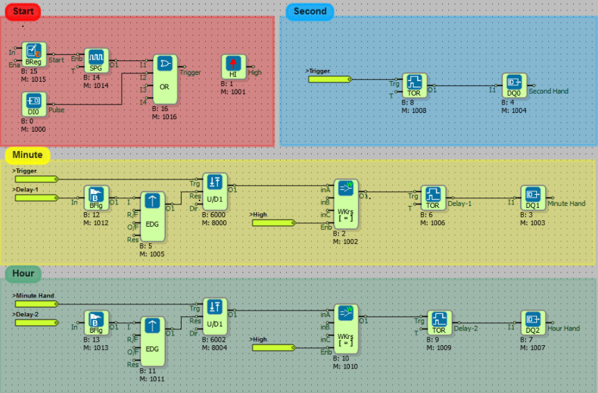
Analog Clock Automation
What You Need to Know Before Design
- DIGITAL INPUT
- DIGITAL OUTPUT
- OR
- HIGH GATE
- BINARY FLAG
- BINARY REGISTER
- SYMETRIC PULSE GENERATOR
- TIMER OUTPUT RELAY
- EDGE
- WORD COMPARATOR
- UP/DOWN COUNTER
- Adding a Line Label
Diagram Algorithm
- A two-armed system is designed to make a circular motion connected to the center.
- The system produces a one-second trigger every six degrees. The process will be repeated in sixty steps.
- The second and minute hands will move 600 milliseconds each on the trigger.
- The hour hand will move five hundred milliseconds every ten minutes. In this way, the clock dial movement within sixty minutes will be carried out gradually.
- The system that will return to the beginning in 12 hours will be realized. The motors that rotate the wheels are stepping motors.
Diagram Solution
- In the system, the input DI0 is the input of the step motor.
- Second hand remains high for 600ms on each trigger (DO0).
- The output of the minute stepper motor is triggered at intervals of 60 seconds (DO1).
- The stepper motor of hour hand is triggered for 500 ms every 10 minutes (DO2). At the end of 60 minutes, the clock dial will progress gradually to one unit.
- When the system is energized, it starts to work automatically.
- If it does not start, it is started with start button.
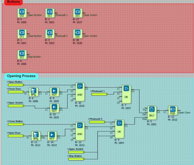
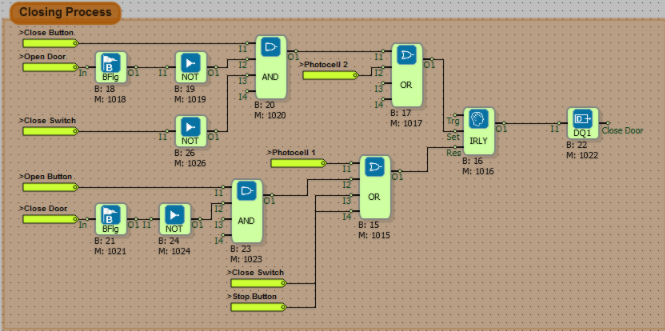
Automatic Door Control
What You Need to Know Before Design
- DIGITAL INPUT
- Adding a Line Label
- AND
- DIGITAL OUTPUT
- NOT
- TIMER OUTPUT RELAY
Diagram Algorithm
- The system will have two start and one stop button.
- The door will open when the first start button (open button) is pressed.
- When the second start button is pressed (close button) the door will close.
- The door will continue to open if the close button is pressed while the door is opened.
- If the open button is pressed while the door is closed, the door will continue to close.
- If the stop button is pressed at any time when the door is open or closed, the door will stop and then whichever button is pressed will move in that direction.
- When the door is closed, the door will be opened if you enter the vehicle. The door will close again after the vehicle has passed.
Diagram Solution
- There are two start buttons that open and close the door.
- The door can not be opened while the door is closed, it can not be closed while the door is opened.
- If the stop button is pressed at any time when the door is open or closed, the door will stop and then whichever button is pressed will move in that direction.
- There are one photocell at the entrance and exit of the door.
- Photocells consists of transmitter and receiver.
- Infrared light communicates between the receiver and the transmitter.
- The receiver and transmitter are mounted mutually.
- The photocell generates an output signal when an object enters between the receiver and the transmitter.
- In this system, when the door closes and the first photocell detects the object, the door stops and starts to open again.
- When the object exits, the second photocell becomes active and the door closes.
- The stop button stops the entire system.
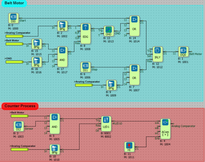
Count Items
What You Need to Know Before Design
- DIGITAL INPUT
- DIGITAL OUTPUT
- ANALOG COMPARATOR
- AND
- ON DELAY
- UP/DOWN COUNTER
- HIGH
- BINARY FLAG
- EDGE
- IMPULSE RELAY
- Adding a Lane Label
Diagram Algorithm
- Products pass through the conveyor belt. When the total product is 500, the system will wait for 30 seconds and it will work again and the same process will be repeated.
Diagram Solution
- In this system, the conveyor belt motor is started with the start button.
- There are bottles in the counter.
- These bottles are counted with the counter.
- When the number of bottles is 500, the belt motor stops in the time defined in the timer (30 sec).
- Then the belt motor continues to work.
- This process is continuous.
Oven Automation
What You Need to Know Before Design
- DIGITAL INPUT
- AND
- OR
- DIGITAL OUTPUT
- WORD COMPARATOR
- IMPULSE RELAY
- EDGE GATE
- BINARY FLAG
- SYMMETRIC PULSE GENERATOR
- UP/DOWN COUNTER
- HIGH
- Adding a Line Label
Diagram Algorithm
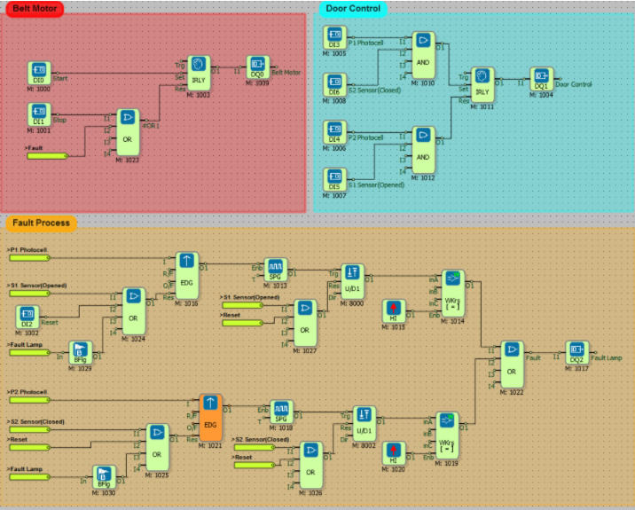
- An oven door is to be controlled automatically by PLC.
- The start button activates the belt motor.
- When the product comes in front of the first photocell (P1), it is requested to open the door automatically by energizing the piston opening bell and to close the door by energizing the piston when the product comes in front of the second photocell (P2).
- The information that the door is open or closed is detected by the S1 and S2 proximity sensors.
- If the product can not be opened within 5 seconds after passing through the P1 photocell, the belt motor must be stopped and the fault signal must be lit. If the door does not close within 5 seconds after the product has passed the P2 photocell, it is still required to turn on the fault signal lamp.
- The belt motor will not move as long as the fault signal lamp is on.
- Fault signal will be reset by reset button.
- Pressing the stop button will stop the operation of the belt motor.
Diagram Solution
- The start button activates the band motor.
- When the product comes in the first photocell, the oven door opens.
- After the product passes through the second photocell, the oven door closes.
- The open position of the oven door is detected by the S1 proximity sensor. If the oven door is closed, it is detected by the S2 proximity sensor.
- If the door is not opened or closed after 5 seconds after the product has passed through the photocells, the alarm will work.
- The alarm is stopped with the Reset button.
- Stop button also stops the belt motor.
Smart Home Application
What You Need to Know Before Design
- DIGITAL INPUT
- AND
- NOT
- OR
- WEEKLY TIMER
- DIGITAL OUTPUT
- RTD INPUT
- HYSTERESIS
Diagram Algorithm
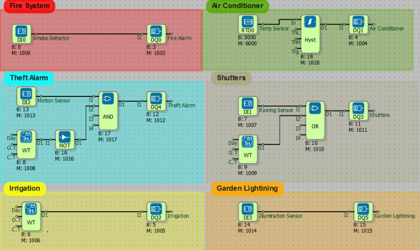
- These applications will be realized by means of sensors, which will minimize the work done by the people living in the home where all kinds of security measures will be taken.
- In the event of a fire possible, the smoke detector will trigger the alarm and fire extinguishing fountains will work.
- The air conditioner will work when the house temperature is above 25 degrees Celsius and will stop when they are below 20 degrees Celsius.
- The grass will be watered every day at 09:00.
- In the evening, the lights in the garden will open.
- In the weekend or after 00:00 at night, the alarm will sound with the motion detector.
- The window shutters will automatically shut down when it rains or between 11 am and 2 pm.
Diagram Solution
- Thanks to the smoke sensor, the fire is extinguished with the mounted fountains.
- The temperature of house is measured by RTD sensor.
- The air conditioner is activated when the temperature is above 25 Celcius degrees and is stopped when temperature is below 20 Celcius degrees.
- The weekly timer block provides daily watering of the grass between 09:00 and 09:30.
- The shutters closes when it is raining thanks to the rain sensor.
- The shutters closes every day between 11 pm and 2 am with the weekly timer.
- The weekly timer block is run against theft on weekends and from 00:00 pm to 08:00 pm on weekdays.
- When the weather is dark, the garden lighting is switched on thanks to the illumination sensor.
Analog Functions
RTD Temperature Control
What You Need to Know Before Design
- RTD TEMPERATURE INPUT
- DIGITAL OUTPUT
- ANALOG REGISTER
- ANALOG COMPARATOR
- HIGH
- SYMMETRIC PULSE GENARATOR
- EDGE GATE
- Adding a Line Label
Diagram Algorithm
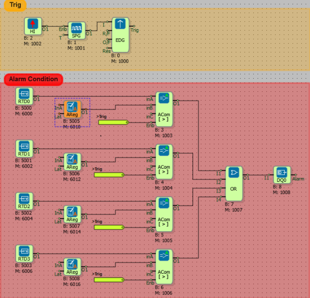
- PT100 data is check with periods 20 second. If over the set value, the digital output DQ0 is activated.
- DQ0 will be inactive when the alarm condition is cleared.
Diagram Solution
- For the desired PT100 sensors to be read, the RTD Temperature Inputs block on the Physical I/O Blocks tab is added.
- The Symmetric Pulse Generator was used to determine the control period of the data from the RTD.
- Since there are four sensors, four analog comparators are used. The sensor data to the inA input of Analog Comparators was connected to the inB input of the temperature value register to be controlled. It was done the comparison trigger by the signal from the Symmetric Pulse Generator.
- The Or gate is used to switch to an alarm state over any temperature sensor.
Analog Table and Operations
What You Need to Know Before Design
- ANALOG INPUT
- ANALOG TABLE
- DIGITAL INPUT
- AND
- ANALOG TABLE OPERATION
- REAL TIME PULSE GENERATOR
- Adding a Line Label
Diagram Algorithm
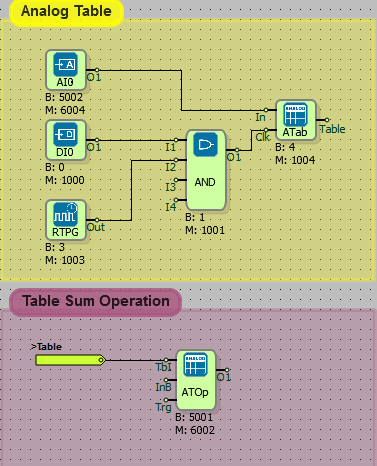
- The analog values read out for periods of five seconds will be collected. The values will be maximum 30 pieces. In the readings above 30 pieces, the first written value will be deleted and the last read value will be written. The system will operate when digital input 0 is activated, it will stop when it is disabled.
Diagram Solution
- Analog input value was be read with AI0.
- If the system is on (when DI0 is in high signal state), the system will be triggered by the signal from the timing trigger and through the And gate.
- An analog table was created with an array of 30 values. Each rising edge to the Clk input of the analog table block will read the new value from AI0. When analog table type FIFO is selected and 30 table size is filled, the last read value will be overwritten with the first read value.
- Analog table operation block also collects the values in the table.
Word Functions
Traffic Lights
What You Need to Know Before Design
- DIGITAL INPUT
- DIGITAL OUTPUT
- HIGH
- OR
- BINARY FLAG
- EDGE GATE
- WORD COMPARATOR
- SYMMETRİC PULSE GENARATOR
- UP/DOWN COUNTER
- IMPULSE RELAY
- Adding a Line Label
Diagram Algorithm
- System will be turned on when to DI0 is pressed,System will be turned off when to DI1 is pressed.
- The light will turn red for 30 seconds, yellow for 10 seconds, green for 20 seconds.
- The system will repeat this process until the Stop button is pressed.
Diagram Solution
- Impulse relay is used to control system on-off. DI0 is connected to the Set Input of the impulse relay namely the activation input. When from DI0 signal is high, system will open.
- DI1 was connected to Res Input of impulse relay. When from DI1 is high, system will close.
- Symmetric pulse generator was used for to create timing algorithm. When the system is turned on, the symmetrical pulse generator will begin to generate signals with periods of one second to be activated. Symmetric pulse genarator is specified 500 milliseconds block that value inside because it produce output at high and low level signal sum period. So, It 500ms+500ms=1 sec will produce output.
- Signals coming from symmetric pulse genarator ıt was counted with counter. Counter operation was used for Up/Down counter. Double click on the block to select the up option. It would count to select up every signal for the coming 0,1,2,3, ... down every signal for the coming 0,-1,-2,,...
- Total burn times for red, yellow and green lights are 60 seconds. When the counter value is 60, the counter is reset because the signalization process will be canceled. the system will repeat the function until system turn off. The binary flag is used because it connects with the timer output to the Word Comparator input.
- The light will turn red in the range of 0-30 seconds, yellow in the range of 30-40, and green in the range of 40-60.
Word Table and Operations
What You Need to Know Before Design
- WORD REGISTER
- AND
- DIGITAL INPUT
- WORD TABLE
- WORD TABLE OPERATION
- REAL TIME PULSE GENERATOR
- Adding a Line Label
Diagram Algorithm
- The word values read out for periods of five seconds will be collected. The values will be maximum 30 pieces. In the readings above 30 pieces, the first written value will be deleted and the last read value will be written. The system will operate when digital input 0 is activated, it will stop when it is disabled.
Diagram Solution
- Word register was connected Word Table input.
- If the system is on (when DI0 is in high signal state), the system will be triggered by the signal from the timing trigger and through the And gate.
- A word table was created with an array of 30 values. Each rising edge to the Clk input of the word table block will read the new value from word register. When word table type FIFO is selected and 30 table size is filled, the last read value will be overwritten with the first read value.
- Word table operation block also collects the values in the table.
GSM Communication Examples
Send Temperature Values via SMS
Things to Know Before Design
- RTD INPUT
- SMS SEND
- WEEKLY TIMER
- STRING REFERENCE
- Adding a Line Label
Diagram Algorithm
- It is requested to send as sms to five numbers determined at 9:00 am on weekdays.
Diagram Solution
- Using the Weekly Timer Block, the system is only activated between 9.00 and 9.15 on weekdays.
- The PT1000 sensor is connected to the RTD inputs.
- For the values read from the temperature sensor, the phone numbers to which the SMS is sent are defined.
- In the 'String table' section, the contents of the message to be sent are written.
- The block number of each RTD Input block is defined by putting a '$' sign at the beginning. For example, $ 5000 is written to the SMS content to read the temperature value from the RTD0 input. The RTD0 input value is $5000, the RTD1 input value is $5001.
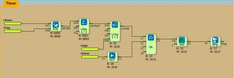
Make Call on Alarm
What You Need to Know Before Design
- RTD INPUT
- BINARY FLAG
- OR
- NOT
- HIGH
- EDGE GATE
- IMPULSE RELAY
- RUN TIME
- LONG COMPARATOR
- LONG MATH
- ON DELAY
- SYMMETRİC PULSE GENARATOR
- DTMF ORIGINATE CALL
- ANALOG COMPARATOR
- Adding a Line Label
Diagram Algorithm
- When a RTD temperature sensor data checked in 20 sec period passes the specified value, DTMF calling will start. Three different numbers will be dialed in order. After calling operation is finished, If temperature value is in location alarm again inside of 30 minute, calling operation will be repeated.
Diagram Solution
- With the analog register, the temperature value at which the alarm condition is generated is determined. With the symmetrical pulse generator, the temperature values are controlled once every 20 seconds. Each of the RTD inputs is controlled by an analog comparator.
- Any analog comparator block output from the analog registers above the specified temperature value will produce a high level signal and go into an alarm state. After going through the alarm condition, the call timer will start to increase at one second intervals.
- If the temperature does not fall within 30 minutes, when the counter value reaches 1800 (1800sec / 60 = 30min), the Ori input will be reset and the calling will start again.
- The calling operation will be performed according to the data received from the analog comparator. If the temperature is between 0-30, the first call will be made, between 100-180 second call and between 200-230 third call.
- The numbers to be dialed are double-clicked in the DTMF Originate Call Block.
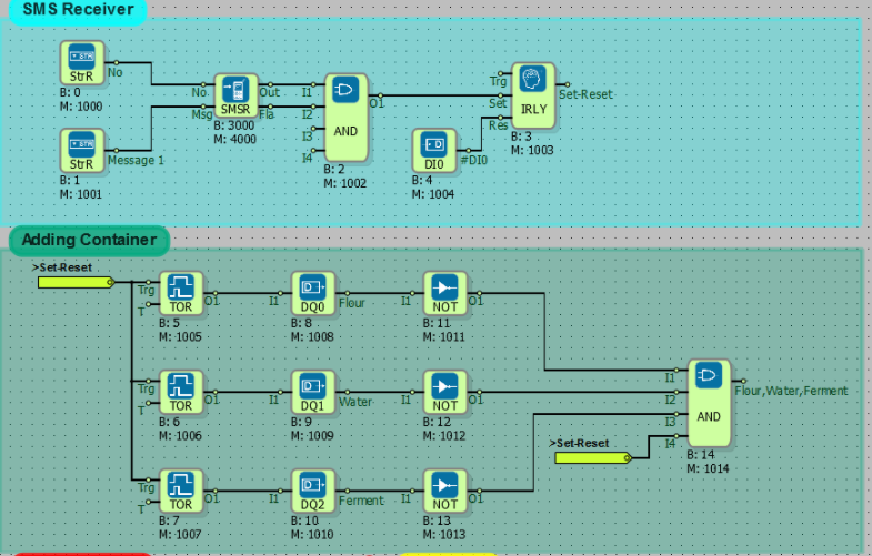
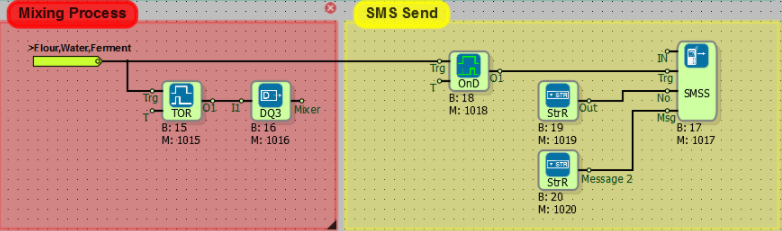
Oven Automation via SMS
What You Need to Know Before Design
- DIGITAL INPUT
- DIGITAL OUTPUT
- AND
- NOT
- SMS RECEIVER
- SMS SEND
- STRING REFERENCE
- TIMER OUTPUT RELAY
- ON DELAY
- IMPULSE RELAY
- Adding a Line Label
Diagram Algorithm
- The system will be turned on at any time by throwing an SMS in the oven project.
- When the message "Prepare dough" is thrown to +441234567890, the system will work.
- On the automation side when commanded, flour is poured into the dough kneading bowl for 50 seconds. Water is added for 20 seconds and the ferment is poured for 10 seconds.
- After the mixture is finished mixture motor will run 15 minute, And then to ovener will be sent " I prepared to dough" message.
Diagram Solution
- From designated number "prepare dough" message, when came will be opened system with impulse relay. The DI0 is connected to the Sif input of the impulse relay to close the system in emergency response or to complete the dough process.
- Timer output relay is used to add flour, water and yeast at different times. The system will become inactive after it has been active for the defined period of time.
- DQ0, DQ1 and DQ2 outputs will be passive after the flour, water and yeast intake is complete when the system is on. These digital outputs are connected to the Not block for producing a high-level signal.
- After the flour, water and yeast are taken, the And gate output will be activated and the mixing will start and the message will be sent after the mixing time is over.
Send Register Values to Internet
What You Need to Know Before Design
- TCP SOCKET BLOCK
- MODBUS TCP SLAVE
- WORD REGISTER
- GSM SIGNAL QUALITY
- GPRS APN
- CSQ
- CONNECTION
- GPRS IP
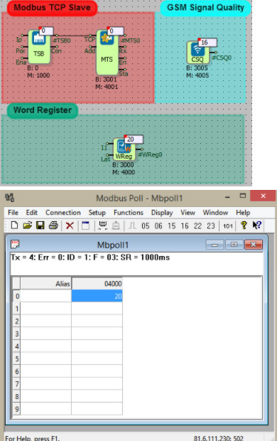
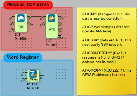
Diagram Algorithm
- Modbus TCP protocol to read and change the word register value via GSM communication.
Diagram Solution
- In the above picture with the online monitoring screen image, the word register data with the modbus address 4000 is read via GSM communication.
- PLC device was arranged server and slave, for GSM connection .
- The server was selected from the TCP socket block and written as listening port 502. The IP filter is not defined because the connection is requested from any IP address. If only one IP was to be connected, an IP filter would have to be specified.
- The Modbus ID number is determined by the Modbus TCP slave block contents. Modbus slave address will allow communication with multiple slave terminals.
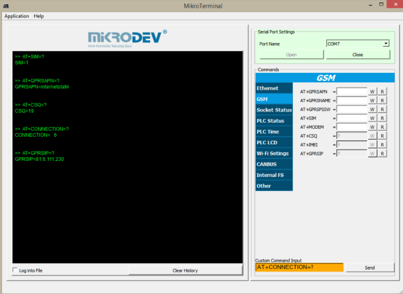
- In order to provide GSM connection, firstly Mikroterminal is opened in Tools section in Mikrodiagram. CSQ, CONNECTION and GPRSIP interrogation must be performed after the APN description is made.
- If the data line used has a static IP address, the APN number that can be learned from the GSM operator must be entered correctly. For example, if the APN address of the GSM operator is 'mgbs', then the AT+GPRSAPN command is typed as 'mgbs' and the write button is pressed.
- To read the quality of the GSM line, press the read button on the AT + CSQ command line. In the example, the CSQ value is read as between 16 and 20. This value indicates that there is enough attraction power to make the connection.
- After starting the GSM line, AT+CONNECTION=? command is sent. If the command reply is '6', GPRS IP is received. AT+GPRSIP=? command is sent to find out the IP address, the device is connected.
Communicating two PLCs via GPRS
What You Need to Know Before Design
- TCP SOCKET
- MODBUS TCP MASTER
- MODBUS TCP SLAVE
- HIGH
- SYMETRIC PULSE GENERATOR
- WORD REGISTER
- MODBUS WORD READER
- GPRS APN
- CONNECTION
- CSQ
- GPRS IP
Diagram Algorithm
- The PLC configured as MODBUS Master will read a register value from the PLC configured as MODBUS Slave. In MODBUS protocol a SLAVE device creates a "TCP Server Socket", however the MASTER device creates "TCP Client Socket". The MASTER device connects the SLAVE device. So the MASTER should know about the IP and PORT information of the SLAVE device.
Diagram Solution
- Two devices and two separate diagrams are used as server and client.
- GSM is selected as the media type in the TCP Socket Block.
- Modbus TCP slave block is used in server diagram. This allows the client device to connect to the server. By specifying the ID, more than one device will be able to operate as a slave. In the TCP socket block, the server is selected and the listening port is entered.
- The MODBUS TCP MASTER block is added on the client diagram to connect to the SLAVE device. Each time the rising edge of the MODBUS word reader block arrives at the trigger input, the specified register is read from the device it is connected to. The ID of the device identified as a slave should be written in the "ID" definition field in the MODBUS word reader block.
- Since the MODBUS register address of Word Register Block with modbus adress is 4000, MODBUS address is set to 4000 in to Modbus Word Reader Block. In the TCP socket of the client device, the IP number of the PLC to be connected and the listening port values are entered. The SLAVE device's IP and listening port values can be learned on the Mikroteminal application console with GPRSIP and LISTENPORT commands.
- You also need to check APN, CSQ and GPRSIP values on Mikroterminal. Please see MODBUS TCP GSM Communication example for connection settings.
Master Device:
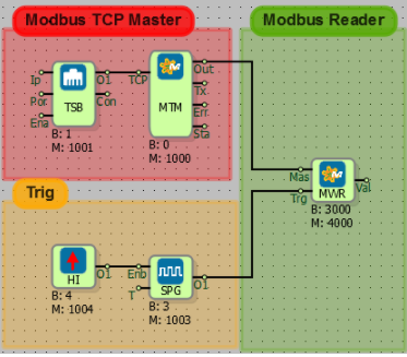
Slave Device:
PLCRESET and GSMRESET Definition via SMS
To use AT commands from mobile, the blocks must be installed as follows.
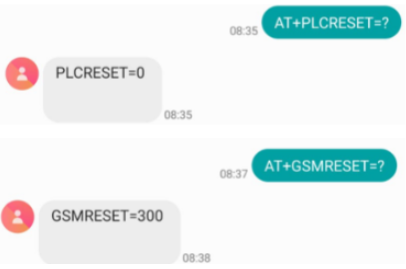
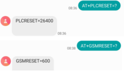
AT+PLCRESET=? and AT+GSMRESET=? When the command is sent, the information stored in the device is sent by the PLC as sms.
When AT+PLCRESET=26400 and AT+GSMRESET=600 command is sent, the specified number is set to the PLC in seconds.
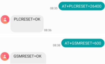
Repeat AT+PLCRESET=? and AT+GSMRESET=? When the command is sent, it is seen that the set value is processed to PLC.
Using SMS Console
Description
You can get and change the data in PLC by sending AT commands from a mobile phone. The following shows sample applications and the transmission of several AT commands.
Example:1
To enable SMS console
To set a string via SMS: Send SMS text message to device in following format:
AT+FBD=Block No,NewTextValue
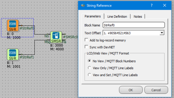
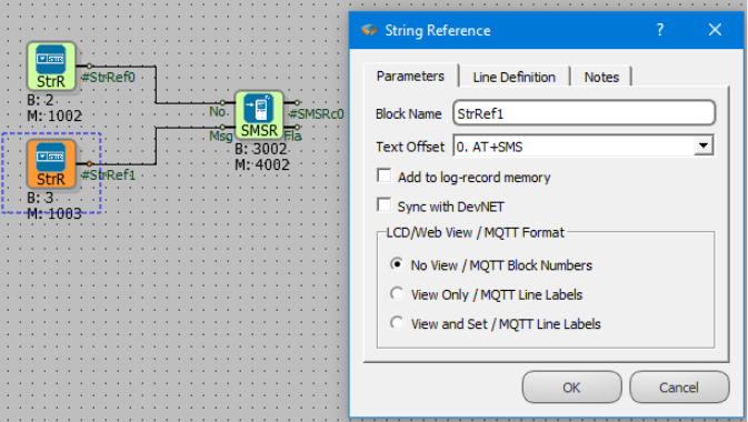
In order to update String Text referenced by String refeecne block (Block No: 2) and String Text Offset 1, send a SMS to device like follows:
AT+FBD=2,+905457878774
Send above SMS text message to the device, to change a string referecence value from remote.
Example:2
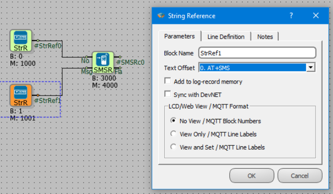
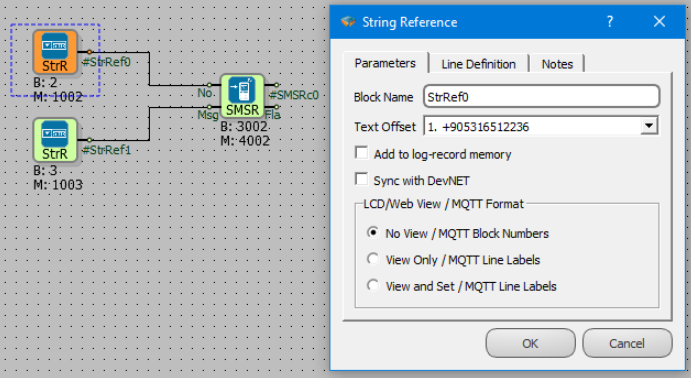
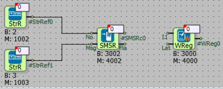
To enable SMS console, select the String Reference Text Offset "AT + SMS" to the SMSR Msj input. Word Register value is 0.
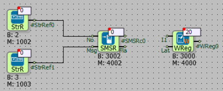
To change the value in the word register, AT + FBD = 3000,20 is sent from Mobil.Word Register value is 20.
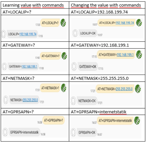
The following table shows the sending and incoming responses of AT commands from the mobile.
Ethernet Communication
MODBUS TCP Ethernet Communication
What You Need to Know Before Design
- TCP SOCKET BLOCK
- MODBUS TCP SLAVE
- MODBUS TCP MASTER
- REAL TIME PULSE GENERATOR
- MODBUS WORD READER
- LOCAL IP
- MAC
- GATEWAY
- NETMASK
- Adding a Line Label
Diagram Algorithm
- The PLC configured as MODBUS Master will read a register value from the PLC configured as MODBUS Slave. In MODBUS protocol a SLAVE device creates a "TCP Server Socket", however the MASTER device creates "TCP Client Socket". The MASTER device connects the SLAVE device. So the MASTER should know about the IP and PORT information of the SLAVE device.
Diagram Solution
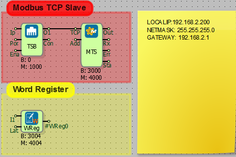
- Two devices and two separate diagrams are used as server and client.
- Ethernet is selected as the media type in the TCP Socket Block.
- Modbus TCP slave block is used in server diagram. This allows the client device to connect to the server. By specifying the ID, more than one device will be able to operate as a slave. In the TCP socket block, the server is selected and the listening port is entered.
- The MODBUS TCP MASTER block is added on the client diagram to connect to the SLAVE device. Each time the rising edge of the MODBUS word reader block arrives at the trigger input, the specified register is read from the device it is connected to. The ID of the device identified as a slave should be written in the "ID" definition field in the MODBUS word reader block.
- Since the MODBUS register address of Word Register Block with modbus address is 4004, MODBUS address is set to 4004 in to Modbus Word Reader Block. In the TCP socket of the client device, the IP number of the PLC to be connected and the listening port values are entered. The SLAVE device's IP and listening port values can be learned on the Mikroteminal application console with LOCALIP command.
- From inside of TCP socket block "TCP server " selecting 502 was written as listening port.Was not write ip filter because you want to connect from any ip address. If only one from IP had to be connected, was will needed IP filter to determine.
- You also need to check MAC, GATEWAY and NETMASK values on Mikroterminal. Please see MODBUS TCP Ethernet Communication example for connection settings.
- Local Ip address, is specified the IP address of PLC device.
- Local Ip setting have to configured subnet mask, default gateway parameters as using.
Master Device:
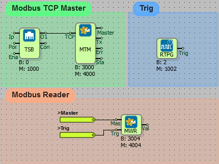
Slave Device:
DevNET Communication
What You Need to Know Before Design
- DEVNET MAIN
- DEVNET REGISTER
- WORD REGISTER
- Adding a Line Label
Diagram Algorithm
- There are two different PLC products connected to the same local network.
- By using DevNET blocks, we will transfer the value of the PLC word register to the DevNET registers of the other device.
Diagram Solution
First Device
- Sync with DevNET must be selected in Word registers.
- Values are entered into Word registers.
- The DevnetMain settings, were looked a pre-design from what needs to be known tab. Timeout and Cycle Delay times are equal since two devices are communicated.
Second Device
- DevNET Main settings for other PLC have been made.
- The address and block number of the device to be read into the DevNET register block are written.
- As you can see in the pictures, the values of the first device's word register are read in DevNET registers of the second device.
Serial Communication
Reading Network Analyser via RS485
What You Need to Know Before Design
- SERIAL PORT BLOCK
- MODBUS RTU MASTER
- SYMMETRİC PULSE GENARATOR
- HIGH
- MODBUS WORD READER
- ANALOG MATH
- Adding a Line Label
Diagram Algorithm
- Reading the voltage data from the network analyzer with RS485 communication port.
Diagram Solution
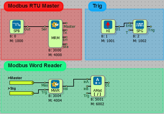
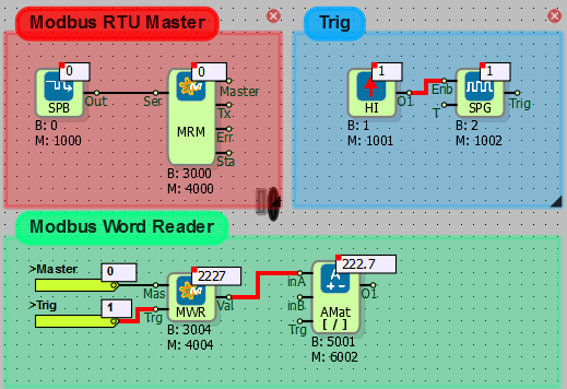
- Serial port and RTU master block are used for serial communication. The Baudrate, Databit and Parity values of the network analyzer are entered in the serial port block.
- Serial port no is entered 0 in the Serial Port Block and Port Type is selected RS485.
- The slave address and register address of the analyzer are entered in Modbus word reader blocks.
- The value is read at every rising edge from the symmetrical pulse generator.
- Since the network analyzer's data is in word format, 222.7 V voltage value is read as 2227. The actual value read from the analyzer screen is accessed by performing a division operation with the Analog Math Block.
Serial Communicating two PLCs via Modbus Table Reader
What You Need to Know Before Design
- SERIAL PORT BLOCK
- MODBUS RTU MASTER
- MODBUS RTU SLAVE
- HIGH
- SYMMETRİC PULSE GENARATOR
- WORD REGISTER
- ANALOG REGISTER
- MODBUS READ/WRITE TABLE
- WORD TABLE OPERATION
- ANALOG TABLE OPERATION
- Adding a Line Label
Diagram Algorithm
Reading of 10 Word and 10 Analog registers in RTU Slave device by RTU Master device via RS485 communication protocol.
Diagram Solution
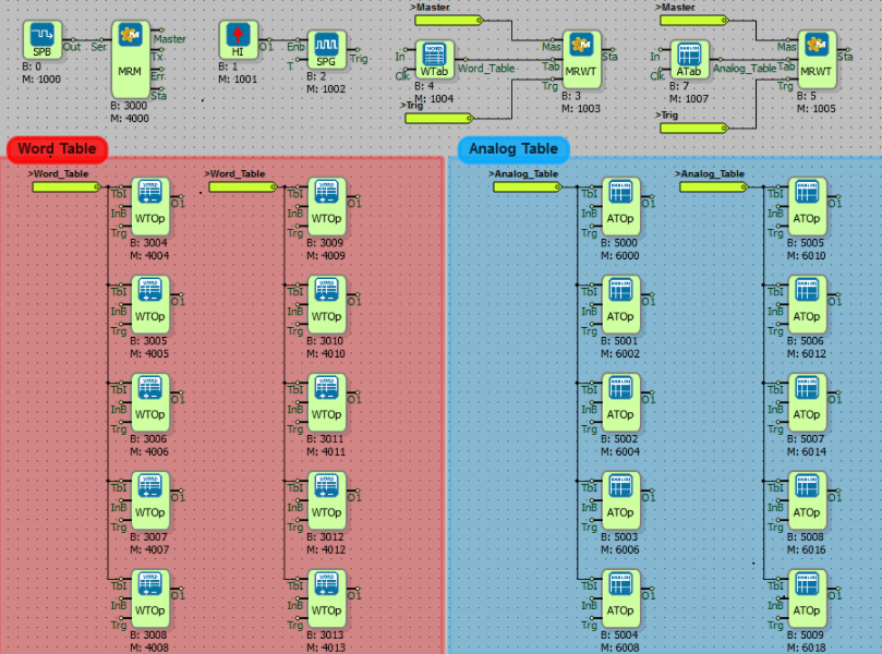
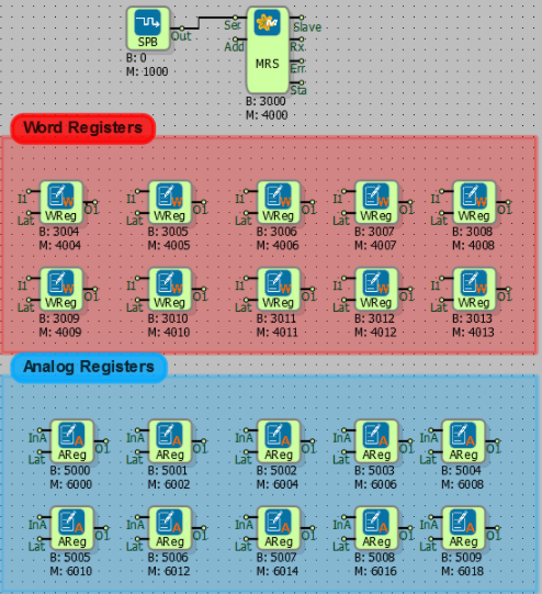
- For the slave device, the Modbus RTU slave block located on the Modbus blocks tab is added.
- Serial Port Block is added for serial communication and communication parameters are set. The slave and master devices must have the same baud rate, data bit and parity option.
- The monitoring screen above is the RTU slave device, and below is the screenshot of RTU Master device.
- For the master device, the Modbus RTU master block located on the Modbus blocks tab is added.
- Since the Modbus table block reads every rising edge, the trigger is sent via the symmetric pulse generator.
- Two modbus table blocks have been used since two different register formats like Word and Analog. Because the word registers start at 4000 and the analog registers at 6000.
- The RTU master line tag has been added to the Mas input of Modbus table blocks.
- The symmetric pulse generator is connected Trg input of Modbus table blocks for trigger.
- For to be read Word and Analog values is added two separate Table Block. The output of table block is connected to the Tab input of the Modbus table block.
- The word table field must be created twice the size of the word register to be read.
- The analog values read from the Modbus table block constitute twice the number of registers read from the RTU Slave. An analog table size is created twice as much as the number entered in the Modbus table block. For example; There are 10 analog registers in RTU Slave. The number of registers in the modbus table read by RTU Master is 20. An analog table block with a table size of 40 is also added for data transfer.
- Modbus table reading function as "0x03 Read Holding Register" must be selected.
- Select "Read Offset" from the operation blocks and the table index number is entered.
- 10 Analog and 10 Word table operation blocks have been added to receive 10 data from Modbus table blocks. This method can also be used by adding two table operation block(for analog and word) and changing the offset value by connecting the register to the "inB" input of the table transaction blocks.
Master Device:
Slave Device:
Digital Control Systems
Ventilation System with PID Control
What You Need to Know Before Design
- DIGITAL INPUT
- ANALOG INPUT
- ANALOG OUTPUT
- PID CONTROLLER
- ANALOG DUAL MULTIPLEXER
- Adding a Line Label
Diagram Algorithm
In the system read with the temperature value RTD0 temperature input, it is desired to control the temperature by the fan connected to the analog output.
PT100 sensor is connected to RTD0 input. Temperature measurement is made between -50 and 100 degrees centigrade.
As the ambient temperature increases, the speed of the fan connected to analog output 0 will also increase.
Ortamın sıcaklığı arttıkça analog çıkış 0'a bağlı olan fan motor hızı da artacaktır. The analog output produces current between 4 and 20 mA. As the motor speed increases, hot air will flow out. This will prevent the heating of the environment.
PID parameters will be calculated with autotunning.
In case of emergency, digital input signal information is received. The analog output value will be reset(4 mA) when a high level signal is input to the digital input 0.
Diagram Solution
- It is predicted that the temperature of the system will be 60 milliseconds.
- The system is run in 'autotunning' mode to set the PID parameters with Autotunning. PID parameters calculated by opening the port from the Mikroterminal console are expected to be displayed. Calculation of PID parameters is provided for 30 minutes by testing the system for possible conditions. The calculation time varies according to the system conditions.
- Once the PID parameters have been calculated, double clicking on the PID block switches the mode option to 'automatic' mode. In automatic mode, the system will continue to operate according to the previously calculated PID parameters.
- An analog multiplexer is used to reset the analog output in emergency situations. If the emergency button is not pressed (DI0), the analog value from the I1 channel of the multiplexer will be transferred to the analog output. When DI0 button is pressed, 4 mA value coming from I2 channel of the multiplexer will be transferred to analog output.
Macro Examples
Define Logical AND Operation on Macro
What You Need to Know Before Design
- HIGH
- SYMMETRIC PULSE GENARATOR
- BINARY FLAG
- BINARY REGISTER
- MACRO
Diagram Algorithm
- Eight binary register values are controlled by the macro with the logical "And" operation.
- Macro block will only work when trig is active.
Diagram Solution
Macro Commands:
[v0=$0&$1] // Evaluate the registers $0 and $1 in the "and(&)" operation and assign the result to variable v0,
[v1=v0&$2] // Evaluate the registers v0 and $2 in the "and" operation and assign the result to variable v1,
[v2=v1&$3] // Evaluate the registers v1 and $3 in the "and" operation and assign the result to variable v2,
[v3=v2&$4] // Evaluate the registers v2 and $4 in the "and" operation and assign the result to variable v3,
[v4=v3&$5] // Evaluate the registers v3 and $5 in the "and" operation and assign the result to variable v4,
[v5=v4&$6] // Evaluate the registers v4 and $6 in the "and" operation and assign the result to variable v5,
[v6=v5&$7] // Evaluate the registers v5 and $7 in the "and" operation and assign the result to variable v6,
[o0=v6+0] // Transfer the value macro block in variable 6 (v6) to the output 0.
[E] // Macro end definition operation
The result of the operation where the value of the register with block no 7($7) is 0 and the other registers are 1:
The result all register values 1:
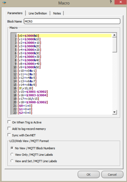
Poligon Valve Linearization
What You Need to Know Before Design
- WORD REGISTER
- ANALOG REGISTER
- BINARY REGISTER
- MACRO
Diagram Algorithm
- The input value is parametrically calibrated at ten different points and transferred to the output.
Diagram Solution
Some sections are explained from within the macro. The entire macro is in the project.
[v0=$3000b0] // Controls whether the value in the register with block number 3000 is equal to or greater than 0. If the condition is satisfied, the v0 variable becomes 1.
[v1=$3000<10] // Controls whether the value in the register with block number 3000 is less than 10. If the condition is satisfied, the v1 variable becomes 1.
[v2=$3000b10]
[v3=$3000<20]
...........
...........
...........
[v20=v0&v1] // Variables 'v0' and 'v1' are subjected to 'And(&)' operation. If the condition is satisfied, the v20 variable becomes 1.
[v21=v2&v3]
..........
..........
..........
[IF,v20,17]
[v30=$3001-$3002] // The value of the register with the block number 3002 is subtracted from the block number 3001. The result is written in variable v30.
[v31=$3003-$3004]
[v32=v31/v30] // The value of the variable v31 is divided by the value of the variable v30. The result is written in variable v32.
[v33=$3000-$3002]
[$0=1+0] // If the block number is 0, the value of the register becomes 1.
[$1=0+0] // If the block number is 1, the value of the register becomes 0.
[$2=0+0]
[$3=0+0]
[$4=0+0]
[$5=0+0]
[$6=0+0]
[$7=0+0]
[$8=0+0]
[$9=0+0]
[$5008=v32*v33] // Variables v32 and v33 are multiplied and written into the block numbered 5008.
[E] // Macro operations end
..........
..........
..........
[E]
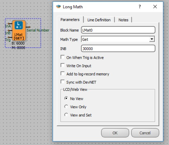
Getting Device Serial Number
You can get the serial number of the device using a "Long Math" block.
The serial number is kept in a special register with address "30000". To be able to access that register you need to use "Get" math operator in "Long Math" block. The following image shows the necessary configuration.
Updating Phone Numbers on Mikrodev Device through SCADA
By using Mikrodev devices, you can send and receive SMS messages(with non-pp* firmwares). The content of the messages and phone numbers are stored in string registers of PLC device. And these strings are configured in PLC project on "string tables".
Sometimes you may want to view and update the phone number for SMS messages through your SCADA system. The following example illustrates how you can achieve this.
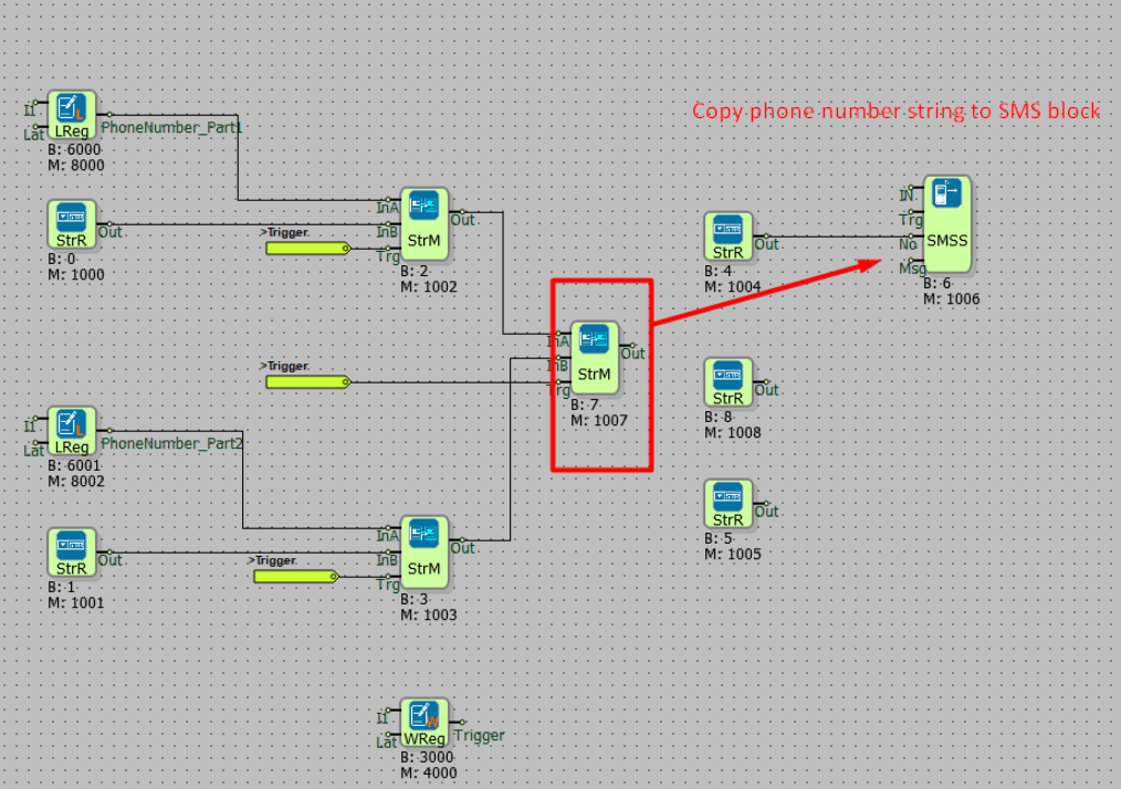
Storing the Phone Number
Since industrial protocols like Modbus only supports numeric data types, you need to store a numeric version of your phone number. And since a single "Long register" is not enough for storing a phone number, this can be done by using "2 Long Registers". You can divide the phone number into 2 parts and write and read these numbers through these registers. But of course; you will also need to convert these "2 Long Registers" containing the phone number parts into a single "String Register". And copy that register into the "phone number input" of SMS block.
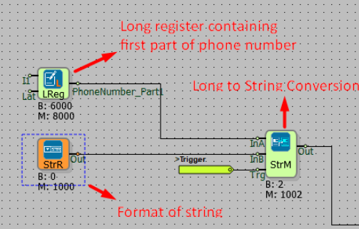
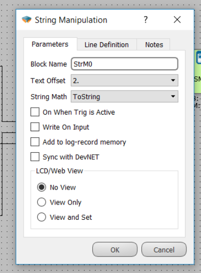
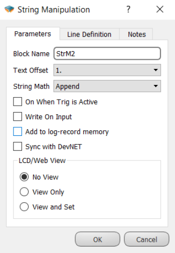
In the "StringManipulation Block" you need to select "ToString" function and write it into a string register, i.e "index 2".
Formatting the Phone Number
In our example; we are using 10th and 11th String indexes as the format input of the phone number parts:
You should take care of these formats and actual phone number parts. They should be in accordance with each other. That means;
If your phone number is like: +905556008899, your configuration will be something like that:
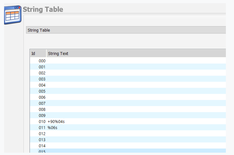
Content of 10th string index: "+90%04s"
Here"%04s" means prepend leading zeros up to 4 digits to your number.
Content of 11th string index: "%06s"
Here"%06s" means prepend leading zeros up to 6 digits to your number.
So if your first long register contains "5556" and second long register contains "8899" these numbers will merged into "+905556008899" by using these formatting rules.
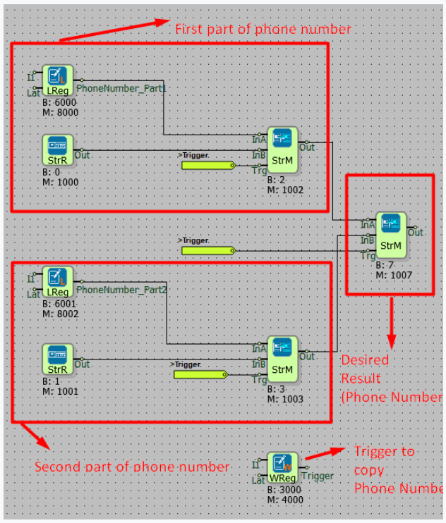
In the "StringManipulation" block below, you should select "Append" operation and copy the result into a string register i.e "index 1"
Running the Logic
After configuring your "phone number string" mechanism, you just need to connect that string into the SMS block and write "1" into the "trigger" register.
View and Update on SCADA
On the SCADA side; you can display "2 Long Registers" in two different components and an apply button for triggering the "trigger" register int the PLC project. The only drawback here is that the user should use the same number of characters as indicated in the format strings in PLC project.
Download the sample PLC project from here
- non-pp firmware: There are 2 types of firmware , default one and the one with point to point networking stack for 3G connection. With point to point firmware you will have higher download/upload speed but no sms or call functionality.
MQTT Communications
Example: 1
MQTT Publish/Subscribe Configuration
What You Need to Know Before Design
TCP SOCKET
MQTT CONFIG
REAL TIME PULSE GENERATOR
WORD FLAG
WORD REGISTER
HIGH
Parameter Settings For MQTT
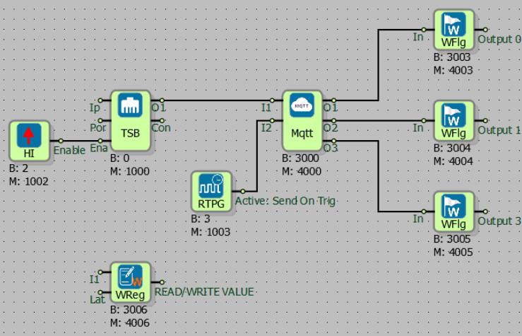
- Client mode must be defined in the TCP socket block for MQTT communication.
- The server ip and port information are entered into the TCP socket block. The media type is selected within the block.
- The Ena input of the TCP socket block must always be active for the duration of the communication.
- After the TCP Socket output is connected to the I1 input of the MQTT Config, verification information such as Client ID, username and password is entered in the MQTT Config Block.
- If Clean Session selection is activated, information is shared when there is communication between publish and brooker. If not selected, the information recorded in the communication breaks will not be sent.
- If there is no communication between the publisher and the broker, the attempt is made to re-establish the MQTT connection in the Keep Alive after the time defined in seconds.
- Timely triggering of I2 input of MQTT Config block is required when periodic data transmission is desired. If there is no trigger for I2 input, the information is sent to the broker according to the defined event conditions.
- According to the information from the o0 output of MQTT Config block, it means: 0: TCP_DISCONNECTED, 1: TCP_CONNECTING, 2: MQTT_CONNECTING, 3: MQTT_CONNECTED
- According to the information from the o1 output of MQTT Config block, it means: 0: E_MQTT_SEND_CONNPACK,1: E_MQTT_STATE_IDLE, 2: E_MQTT_STATE_SUBSCRIBING, 3: E_MQTT_STATE_PUBLISHING
- The publish tmo information is read from o2 output of MQTT Config block.
Event Definitions in MQTT Table
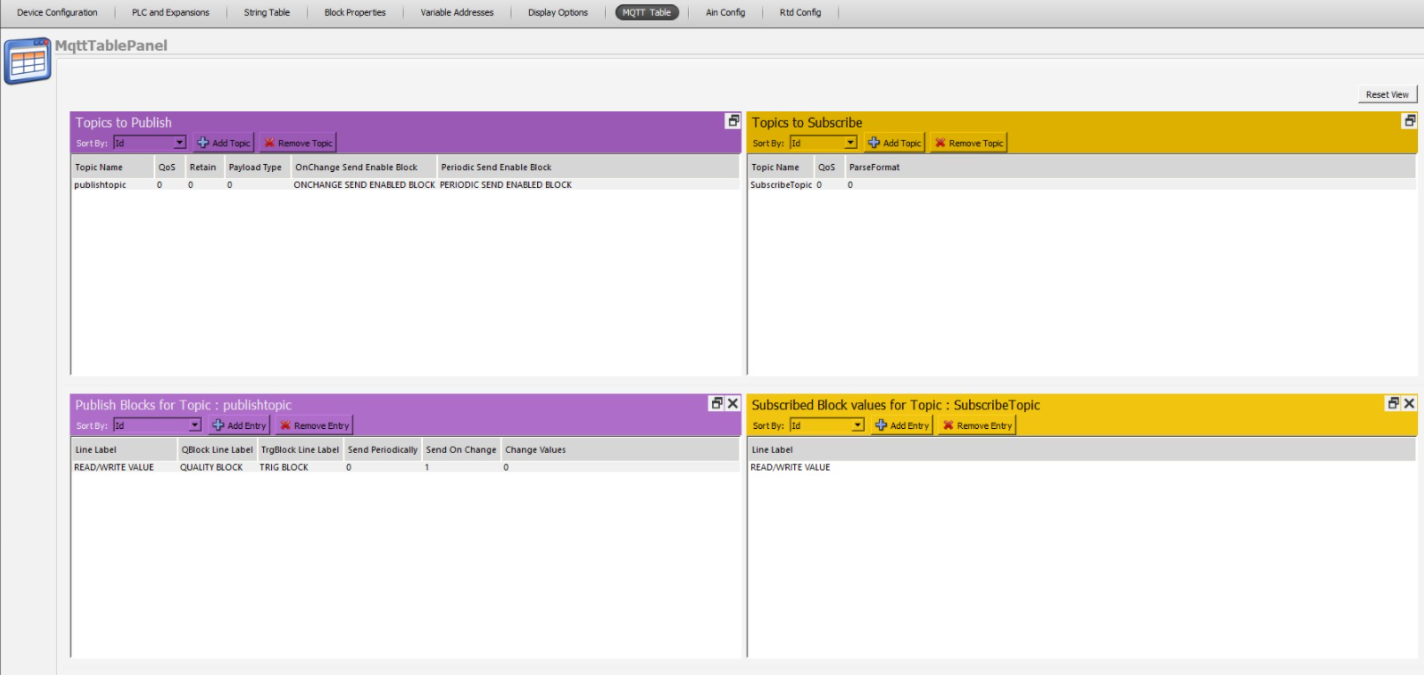
- In the Topic to Publish section, you can turn on and off the send options with Onchange send enabled block and periodic send enabled block, the block must be attached here. If the block value is 1, the send option is active, if it is 0, the send option is disabled. Qblock line label and Trgblock line label have been added in the publish to block for topic section. A qaulity information that can be determined by the user is sent together with the data to be sent with Qblock, can be left blank. With the trg block, it is possible to send a different trigger, regardless of sending a periodic, and leave it blank.
- To create event definitions, click 'MQTT Table' option in 'Projects' in Mikrodiagram or Telediagram Program.
- In the Topic to Publish section, the topic title to be published is entered. Payload type is selected. The query status of the package to be published in the QOS section is determined. If QOS 0 is selected, the status of the package to be publisher is not queried. If QOS1 is selected, it is informed that broadcast package is transmitted. If QOS2 is selected, the broker will receive feedback on the delivery of the published information. If retain is selected and the communication between publish and broker is lost, the latest information is kept in memory. When communication is established again, the last information is published. If clean session is selected in MQTT Config block, the information will not be published again even if retain is selected.
- In the Publishtopic section, the blocks to be published are selected. By selecting the line tag, it is determined in which case the data will be sent. If Send on trigger is selected, the data will be published according to the trigger for I2 input of The MQTT Config block.
- In the Topics to Subscribe section, a topic title is created for the tags to be subscribed. The verification status of the subscribed information is selected (QoS0, Qos1, Qos2).
- In the Subscribe Topic section, the information to be subscribed is selected.
Example: 2
Mikrodev device sends the MQTT data in the following format:
{"BLOCKNUMBER1":VALUE1} or {"LINELABEL1":VALUE1}
for multiple values :
{"BLOCKNUMBER1":VALUE1 , "BLOCKNUMBER2":VALUE2} or {"LINELABEL1":VALUE1 , "LINELABEL2":VALUE2}
As an example, if you have selected blocks with block numbers 3001 and 6001 under a topic the device will send the following strings:
{"3001":1234, "6001":123.6 }
You can also use "Line Labels" instead of "Block Numbers" in the JSON format. "Block Number" or "Line Label" display format selection is made within the block properties.
Using LCD on MP211 Series
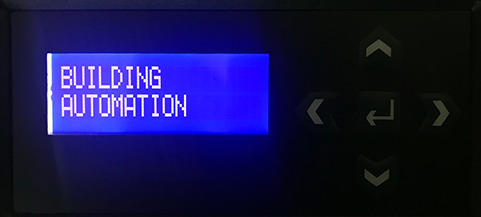
Setting Welcome Text
The Mikroterminal application is used to change the text that appears on the LCD screen when MP211 is energized first time. After starting Mikroteminal application, you can change the upper line by entering the command 'AT + MENULINE1 =' and lower line by entering the command 'AT + MENULINE2 ='. The text will change when you send the command to the device after typing any word at the end of these commands.
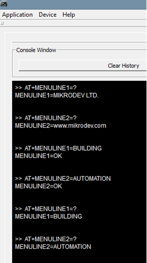
Example:
AT+MENULINE1=BUILDING
AT+MENULINE2=AUTOMATION
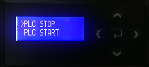
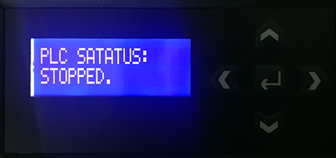
Start/Stop Control
To start or stop PLC process select "PLC CONTROL" on the LCD screen using the arrow buttons on the keypad. And choose "START" or "STOP". The PLC will behave accordingly.
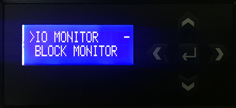
Monitor I/O Values
You can monitor the real-time values of Inputs and Outputs by selecting "IO MONITOR" on the LCD screen using the arrow buttons on the keypad.
Selecting Blocks for Online Monitoring
You need to select the 'LCD/Web View' option in Mikrodiagram for the blocks which you want to view/control on LCD screen. If you only need to monitor the value select "View Only". If you also want to be able to modify the block value via LCD and keypad select "View and Set".
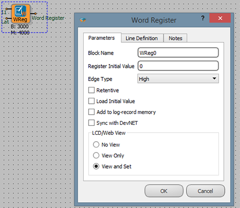
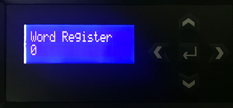
And you also need to define a "Line Label" for these blocks. "Line label" string will appear on the LCD with its real-time value.
Modifying Register Values
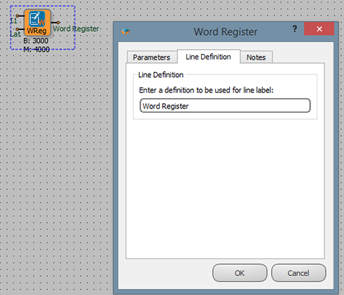
To set a register value; select "BLOCK MONITOR" on the LCD screen using the arrow buttons on the keypad.
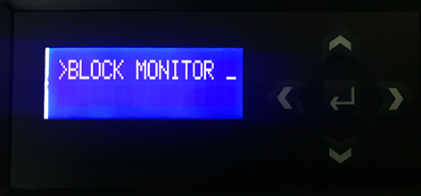
And select the block which you want to set value.
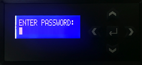
After entering the password, you can enter a value for the block. If you haven't set a login password for the device yet, just enter "0" value as password.
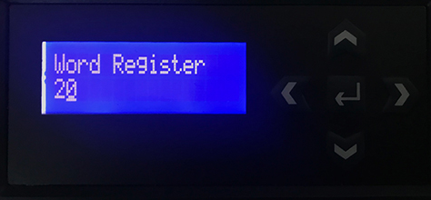
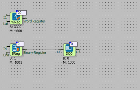
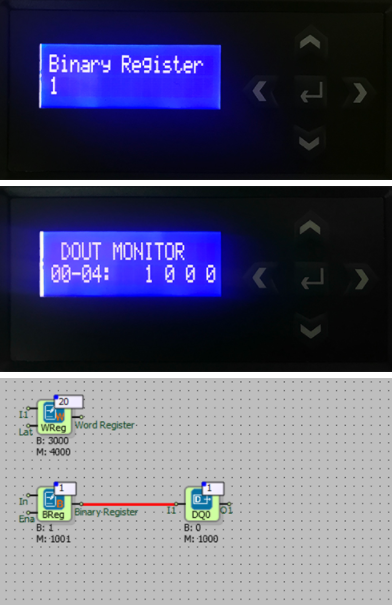
Example
In the following example, the output of the binary register is connected to the input of the digital output(DO0). Digital output(DO0) is activated by writing a (high) binary register value on the LCD screen.
DNS Block
DNS Block Usage

Block Custom Settings
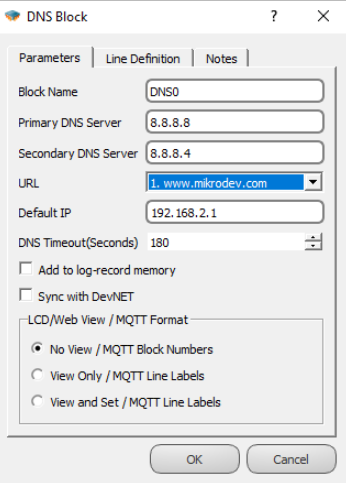
Blok Name: The name of the block.

Primary DNS Server: The Primary DNS server is entered in this section.

Secondary DNS Server: Secondary DNS Server is entered to this section.

URL : The URL to use is entered in the string table. The ID of the URL entered in the string table is selected here.

Default IP : Default IP is entered in this section. If the DNS block cannot convert the URL to the IP address, Default IP is used.

DNS Timeout : The DNS timeout value is entered in this section
String Table Entering Value
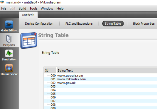
Click the Projects tab on the left of the Mikrodiagram software. String Table is selected from the top menu.
You can enter a URL under the String Text heading.
Use with TCP Block
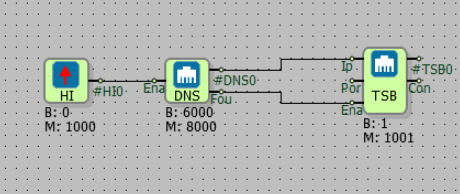
The dns block output is connected to the ip pin of the tcp socket block. The DNS block will convert the URL to IP, Fou. pin is active. The tcp block uses the ip address from the DNS block.
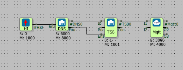
The TCP socket block can be used with the Mqtt block.