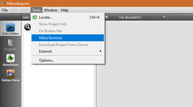
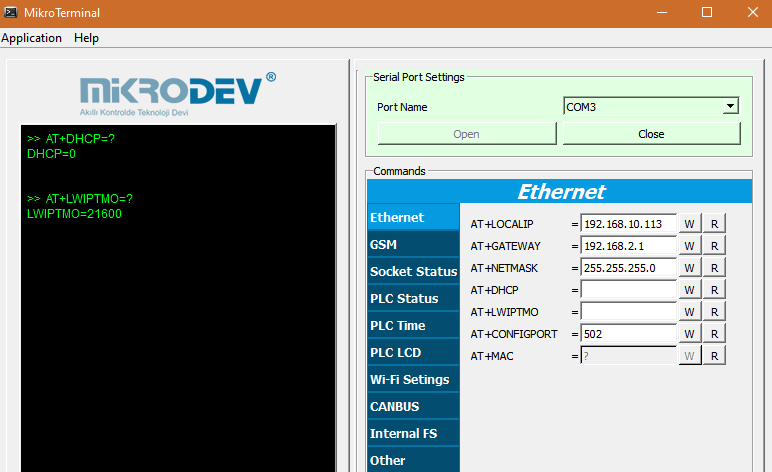
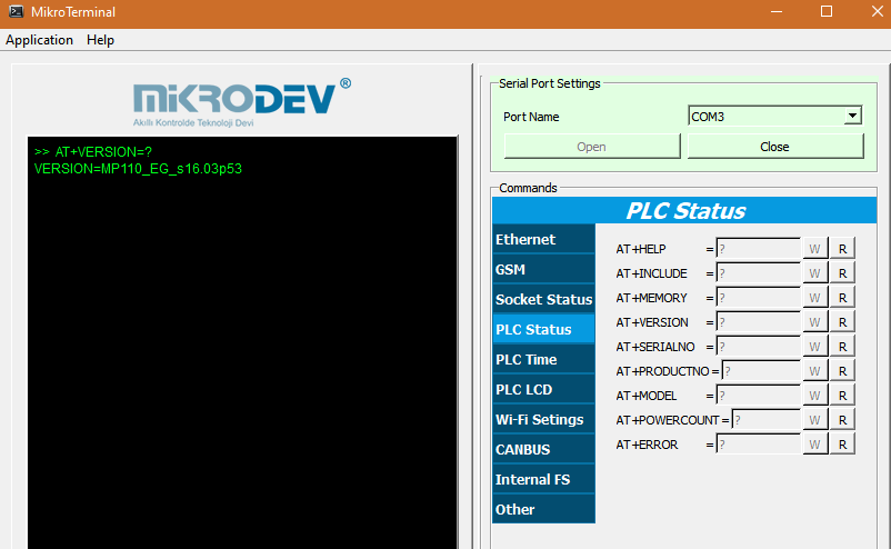
Mikroterminal Interface
The mikroterminal program can be accessed from Mikrodiagram Tools menu.
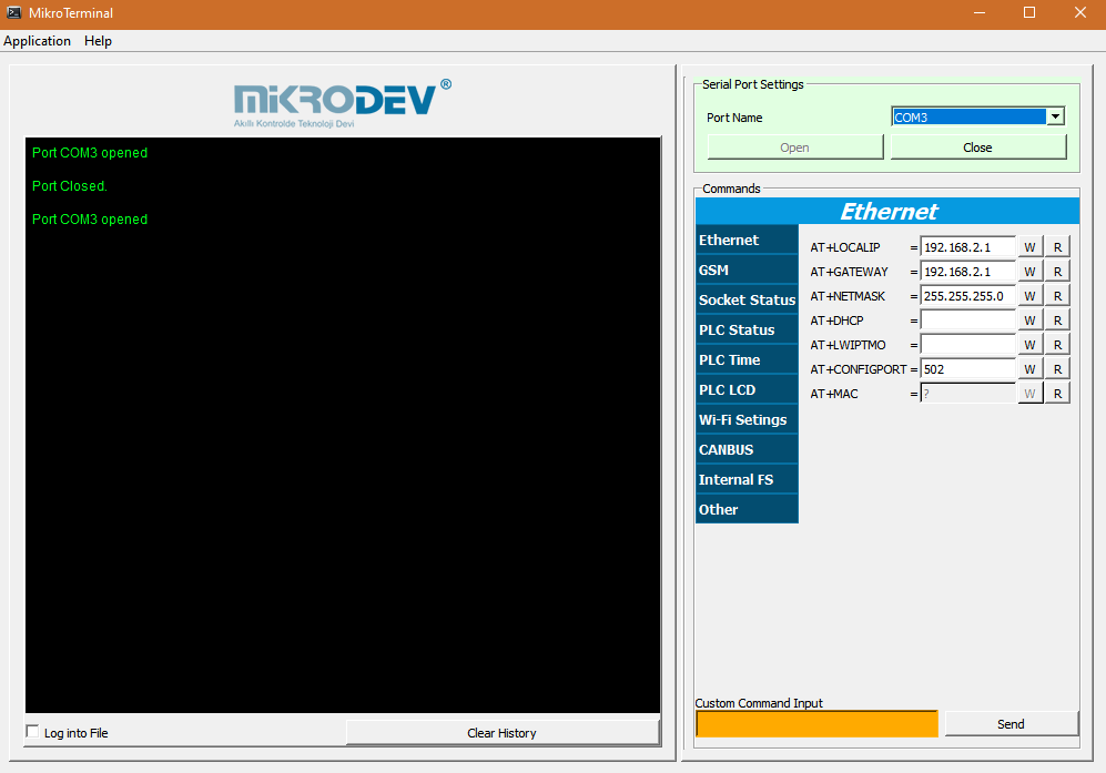
- Opening the USB COM Port
To open the COM port on the mikroterminal, select the port where the connection between the device and the computer is established in the "port name" section. (The connection port between the device and the computer can be controlled from the "device manager".)
When the "Open" tab is clicked, the COM port information displayed in the "console window" is displayed.
- Sending The AT Command
With AT commands, the current settings on the device can be read or the desired values can be written to the device.
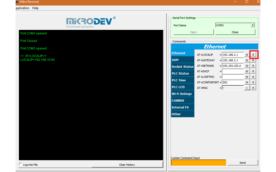
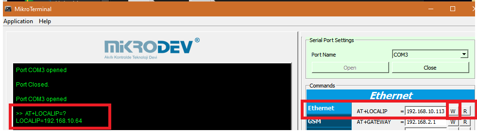
Click on the "Read" button to read the current settings on the device. When the "Read" button is clicked, the current value in the device is displayed in the "console window".
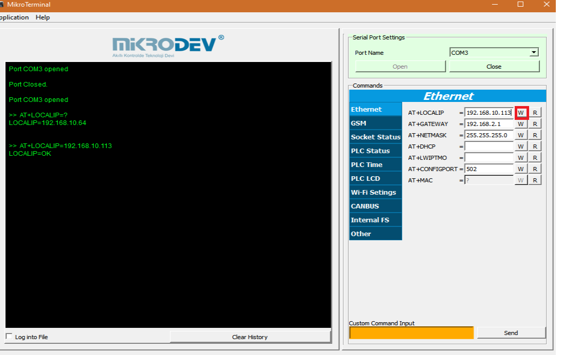
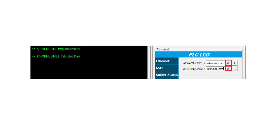
In case the current settings of the device are to be changed by AT commands, the value to be changed is written on the window, then the "Write" button is clicked. The value written is displayed in the "console window". If the write operation is successful, the command “OK" is printed in the console window.
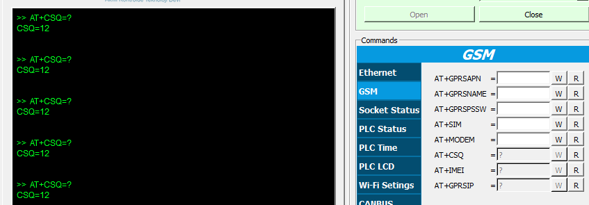
- Custom Command Window

AT commands can also be sent from the custom command input window.
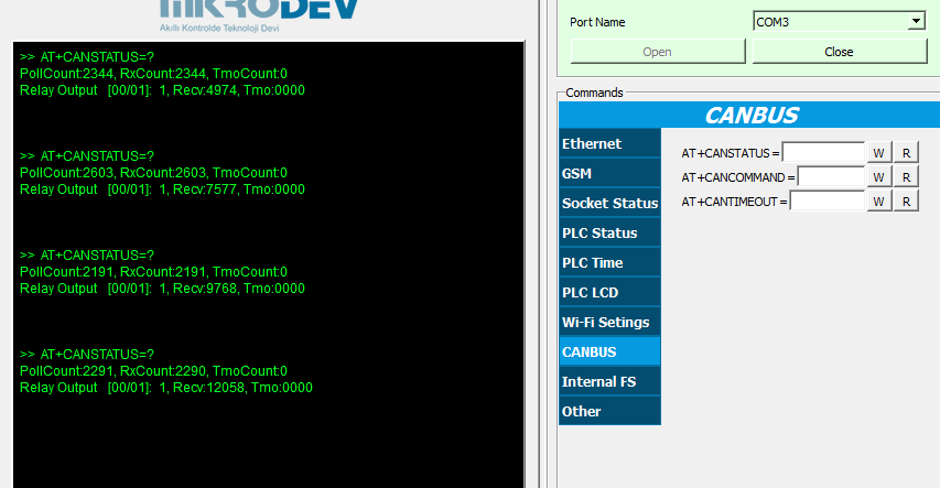
If the current value in the device is to be read, the window "AT + SPECIALTY =?" is written, the "send" button is clicked, the current value is displayed in the console window.
If you want to write a value from the device specific command window, the command "AT + SPECIALTYPE = WRITE COMMAND" is defined and the value written when the "send" button is clicked is displayed in the console window.
If the write operation is successful, the command "SPECIALTY = OK" is printed in the console window.
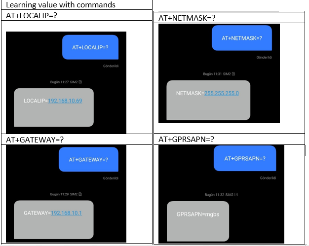
List of The AT Command
Ethernet
- AT+LOCALIP
Used to identify local IP to devices with Ethernet or Wi-Fi capability
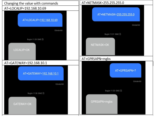
To change the local IP, type "AT + LOCALIP = IP" and click "write" command to write IP to the device.
Click on the "read" command to read the current IP value.
- AT+GATEWAY
It is used to define gateway to devices with Ethernet or Wi-Fi capability.
In a local network, the gateway is usually the IP address of the modem.
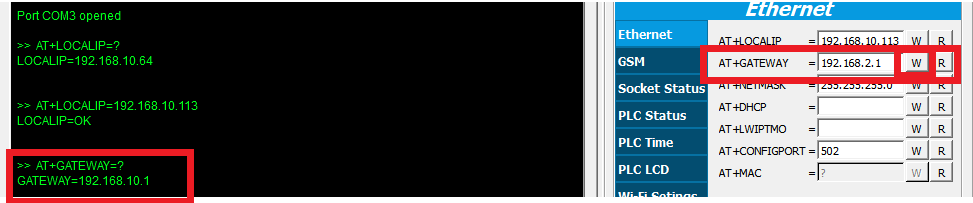
AT + GATEWAY "command to read and write the gateway address.
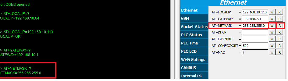
- AT+NETMASK
It is used to define "netmask" for devices with Ethernet or Wi-Fi capability.
- AT+DHCP
AT+DHCP= Enable/Disable DHCP.
• AT+DHCP = 0 – Disable
• AT+DHCP= 1 – Enable
- AT+LWIPTMO
If no packets received from PLC Ethernet port, resets the Ethernet connection.
- AT+CONFIGPORT
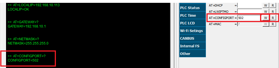
The AT + CONFIGPORT command is used to identify the port number used in situations where a TCP port connection from Mikrodiagram is desired to be installed on devices with a TCP communication port (Ethernet, GSM, Wi-Fi).
The factory default ConfigPort number is 502.
It can be changed with AT + CONFIGPORT command.
AT + CONFIGPORT = ? command can be viewed with the current configport.
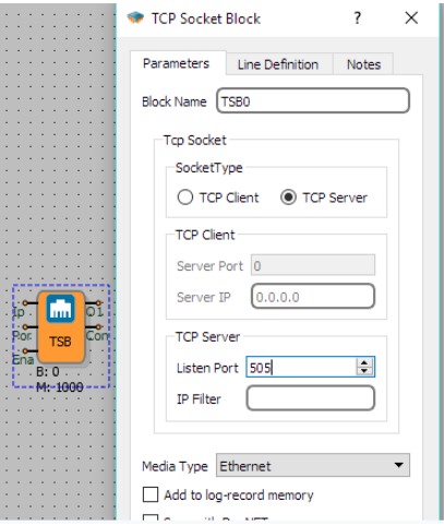
CONFIGPORT is disabled when a selected TCP socket block is added to the device as a server Mikrodiagram. The device's listening port is the listening port that is inserted into the TCP socket block.
- AT+MAC
It is used to define the MAC address for devices with Ethernet or Wi-Fi capability.
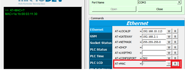
The current MAC address can be read with "read" command.
GSM
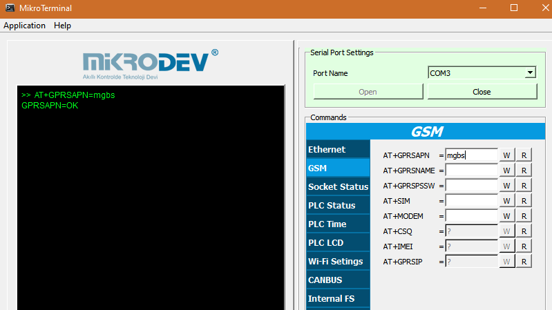
- AT+GPRSAPN
AT + GPRSAPN command is used to define APN for Mikrodev products with GSM TCP communication feature.
Since the APN that needs to be defined varies according to the SIM card operator used in the device,it must be supplied from the customer service of the relevant GSM operator.
The APN has to be defined if the used device is to be used as a server in the TCP communication with the GSM line (if the device will connect to another IP).
Note: The SIM card used in the APN-defined device must have a static IP.
Note: GPRSAPN Settings
- for Turkcell - mgbs
- for Vodafone - internetstatik
- for Türk Telekom - statikip
- AT+SIM
It is used for SIM card inquiry in Mikrodev products with GSM hardware.
With "AT + SIM =?" read only command. The value can not be written.
The response to the command is SIM = 0 to indicate that the SIM card is not inserted, is incorrectly installed or is defective.
If the answer to the command is SIM = 1, it indicates that the SIM card is correctly installed and is fault-free.
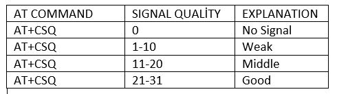
- AT+CSQ
It is the value of the GSM signal quality (the power of the GSM line) that the devices with GSM capability are installed. It can be between 0 and 31.
Even if the SIM card is not inserted, the value can be read while the GSM antenna is connected. (Emergency calls are used on mobile phones when the SIM card is not inserted.)
AT + CSQ is only readable command.
The pull chart is as follows.
- AT+IMEI
It is used to find out the IMEI number of the SIM Card.
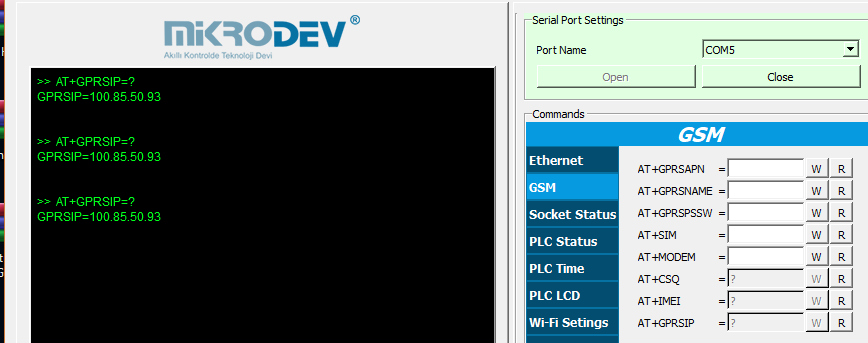
- AT+GPRSIP
The data package (internet package) is the IP of the SIM card. Supplied by the GSM operator.
It can only be read by AT + GPRSIP command.
If the device is to be used as a server, a SIM card with a fixed IP address must be provided.
When a SIM card with a fixed IP is provided, APN information must also be received from the GSM operator.
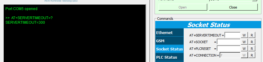
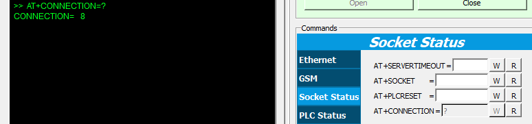
Socket Status
- AT+SERVERTIMEOUT
If the connection between the device and the remote system is lost or the connection between the devices is lost, it is waited for the specified second and then used to reset the device.
- AT+SOCKET
It is used to monitor the active connections of TCP socket blocks in Mikrodiagram project.
When AT + SOCKET = <"TCP Socket Block" Block Number> command is sent to the device, the connections made from the relevant TCP socket block are displayed.
Those with status "1" indicate that the connection exists. The "status" states, which are different from "1", indicate that the link already existed, but that the link broke down before the specified time.

- AT+PLCRESET
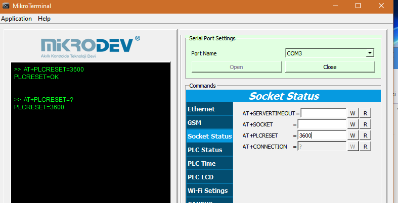
The AT + PLCRESET command is used when TCP communication protocols require the device to be reset after a certain period of time.
If AT + PLCRESET = 0 command is sent to the device, the command is disabled.
The AT + PLCRESET command runs at a minimum 60 second (sec) scale.
To learn the current PLCRESET command programmed in the device, enter AT + PLCRESET =? command can be sent to the device.
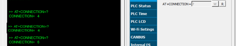
- AT+CONNECTION
Connection status check of Mikrodev products with GSM data exchange feature is done by "AT + CONNECTION" command.
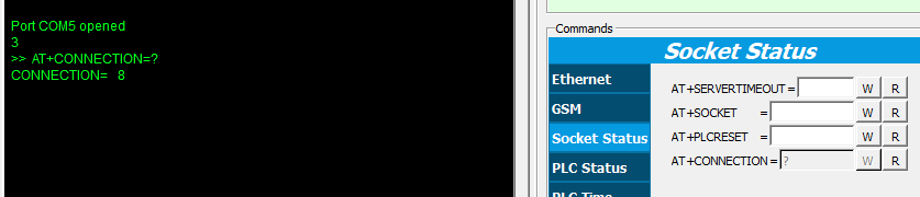
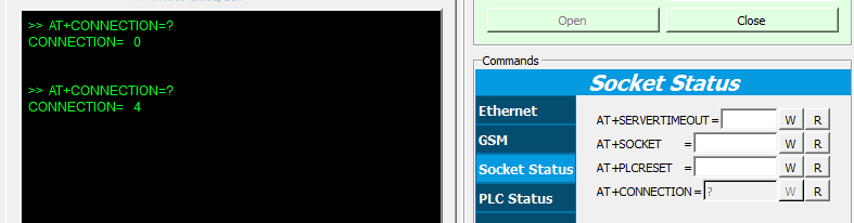
The AT + CONNECTION command has only readability.
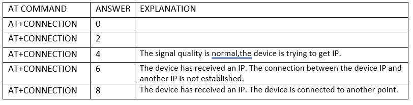
The AT + CONNECTION command receives even-numbered values 0-8.
The AT + CONNECTION command response table is below.
PLC Status
- AT+HELP
It is the command that indicates which queries can be asked to the device.
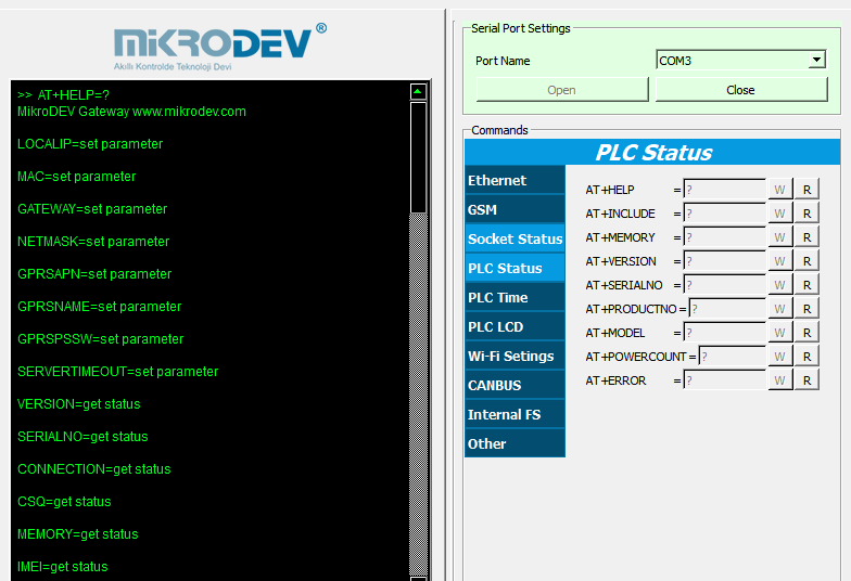
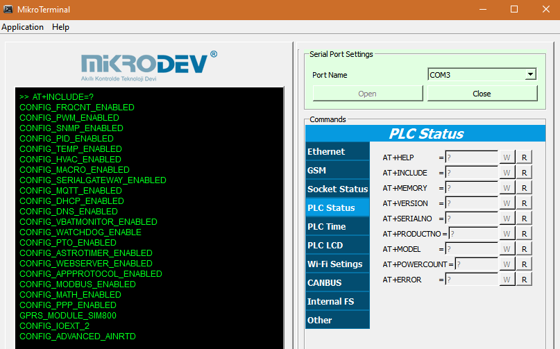
- AT+INCLUDE
It is the command that shows which features are active or inactive on the device.
- AT+VERSION
It is the command that shows the version information on the device.
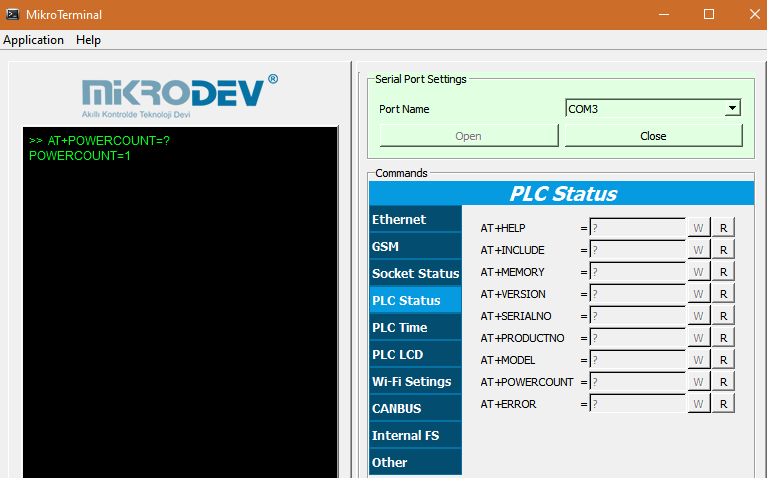
- AT+POWERCOUNT
It shows how many times the device is restarted after Mikrodiagram project is loaded. The first value is 1 since the device is restarted after the mikrordiagram project has been loaded.
Readable command.
AT + POWERCOUNT= ? , The current value is queried.
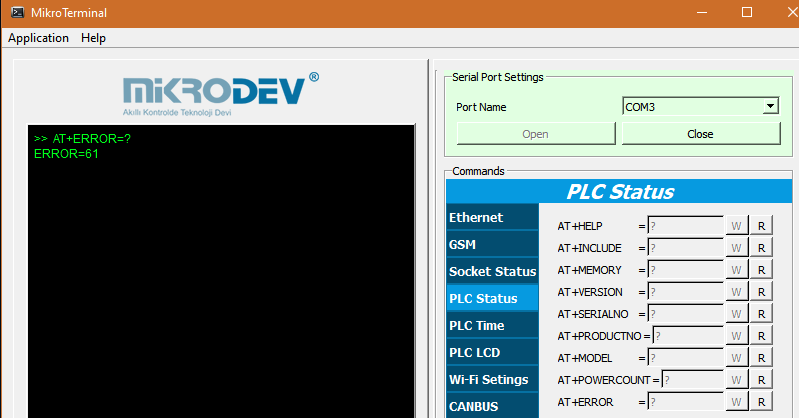
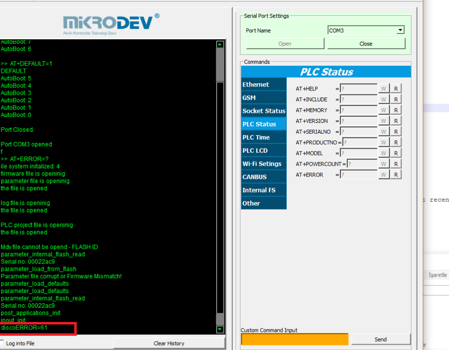
- AT+ERROR
If the device is in error mode, it is used to learn the error code.
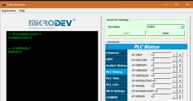
If AT + ERROR = 0, then there is no error condition.
AT + ERROR = 61 means that the device does not have Mikrodiagram installed
The AT + ERROR command is only a readable command.
PLC Time
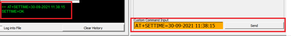
- AT+SETTIME
With the AT + SETTIME command, the device real time clock can be read and written.
When the AT + SETTIME command "read" is clicked, the current time of the device readable in the console window, the date and time to be set to the command window; When set to "dd-mm-yyyy hⓂ️s" and the "summer" command is sent, the time set is displayed in the console window.
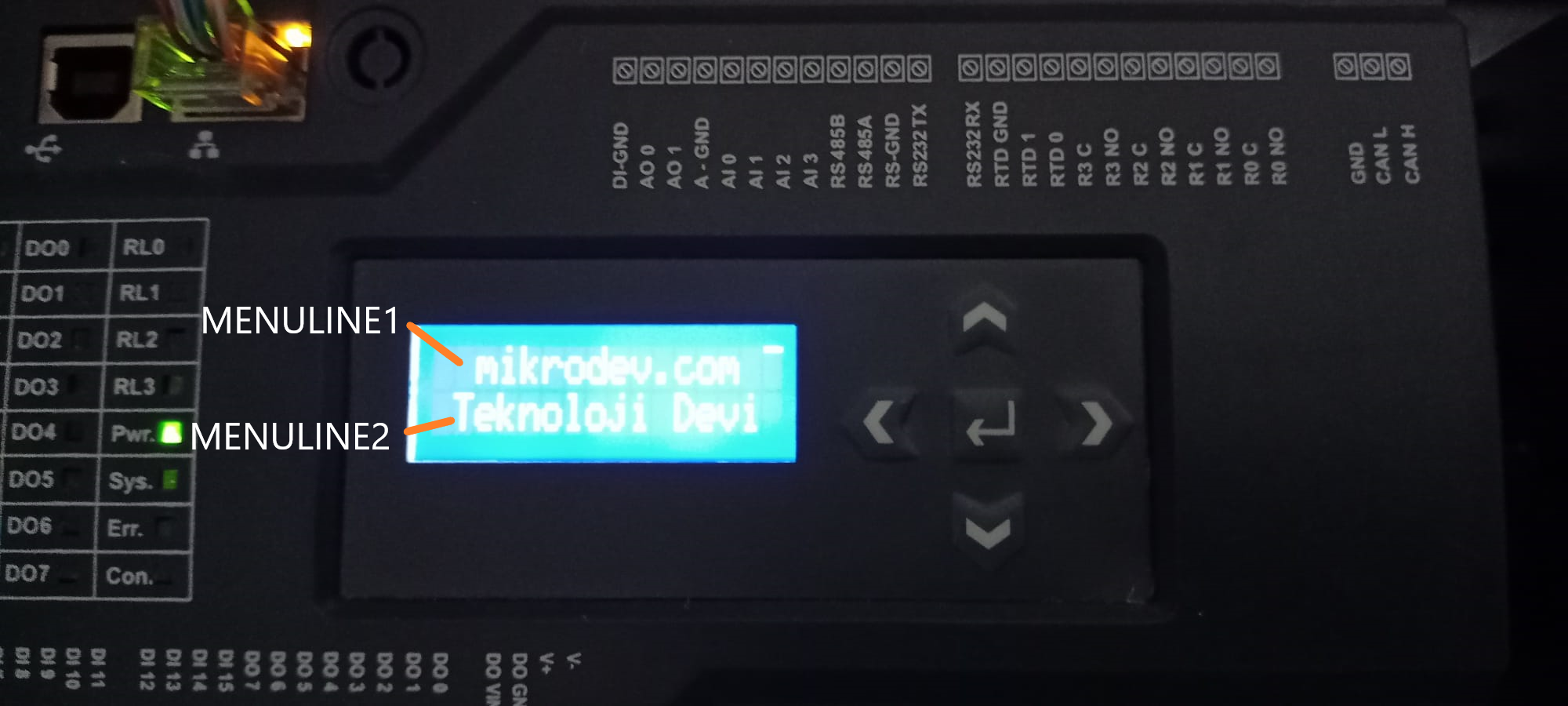
PLC LCD
- AT+MENULINE1
- AT+MENULINE2
WIFI Settings
- AT+WIFISSID
It is used to identify the WI-FI network name to be included in WI-FI enabled products.
In the "AT + WIFISSID" command window, the WI-FI name is written, the "write" command is clicked,
When you want to read the current WI-FI SSID, click "AT + WIFISSID" "read" command.
- AT+WIFIPSSW
It is used to describe the password of the WI-FI network to be included in WI-FI-enabled products.
AT + WIFIPSSW WI-FI password is written into the command window, click on the "write" command,
When the current WI-FI password is desired to be read, the AT + WIFIPSSW "read" command is clicked.
CANBUS
- AT+CANSTATUS
It is state learning command for Mikrodev Expansion Devices.
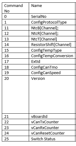
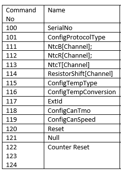
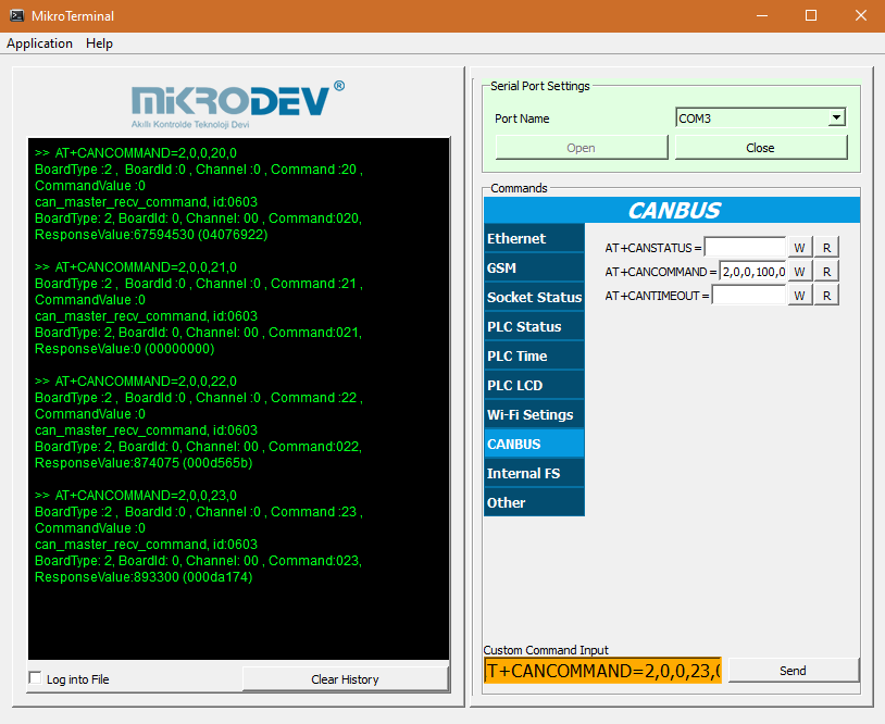
- AT+CANCOMMAND
With the AT+CANCOMMAND query, information about the expansion device can be accessed.
AT+CANCOMMAND=< BoardType >,< BoardId >,< Channel >,< Command >,< VALUE >
• BoardType:
- XIO211_DIN = 0,
- XIO211_DOUT = 1,
- XIO211_RELAY = 2,
- XIO211_AIN = 3,
- XIO211_AOUT = 4,
- XIO211_RTD = 5,
- XIO211_DI8DQ8= 6,
- XIO211_DI8= 7,
- XIO211_DQ8= 8,
- XIO211_AI4AQ4= 9,
• BoardID:
Board value set with DIP Switch.
• Channel:
The corresponding channel number in the expansion. For example, if it will calibrate the 3rd input on the analog input, 2 will be written here.
• Read Commands:
• Write Commands:
- AT+CANTIMEOUT
AT + CANTIMEOUT command Mikrodev is used to protect the position of the inputs and outputs on the expansion units for a specified period of time in case of communication failure between CPU modules and expansion units.
The CANTIMEOUT time runs in millisecond (ms) time scale.
When the communication link between the input modules and the CPU breaks, inputs up to the number of CANTIMEOUT entered into the CPU do not change position in the software.
When the communication link between the output modules and the CPU breaks, the outputs do not change positions as long as the CANTIMEOUT times entered in the output modules.
The CANTIMEOUT time input to the CPU is used for the input modules, the CANTIMEOUT time input to the output modules for the output modules is used.
For example, if AT + CANTIMEOUT = 60000 (ms) is defined for the CPU and expansion units, the incoming digital input signal position is maintained through the expansion unit until 60000 (ms) (1 minute) after communication between the digital input (DI) expansion unit and the CPU is interrupted. 60000 ms. After the CANTIMEOUT time has elapsed, the digital inputs are pulled to logic (0) if no connection to the expansion unit is still present.
Internal FS
- AT+FBD
In Mikrodiagram, it is used to read block value and write block value by using "block numbers" of door types.
If the value is to be written, "AT + FBD = BLOKNO, VALUE" is defined and clicked on the "write" command.
If the block value is to be read, "AT + FBD = BLOKNO,?" is defined and clicked on the "write" command.
The "read" command is not used in the AT + FBD command, only the "write" command is used.
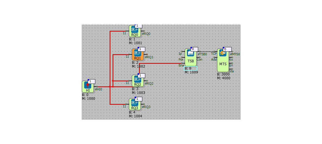
Example;


Since the 3000 no of block is a register block, both writing and reading can be done.
When "AT + FBD = 3000,10" is entered and "summer" button is clicked, "10" value is written on block. Value information written is displayed as "FBD = OK" in the console window.

If you want to read the block value of no 3000 , "AT + FBD = 3000,?" is written and when the "write" command is clicked, the block value is displayed as "FBD = 10" in the console window.
- AT+ONLINE
It is used to start and stop the online viewing from the mikroterminal while online viewing is performed in Mikrodiagram.
Online monitoring is started when AT + ONLINE = 1 command is sent.
Online monitoring is stopped when AT + ONLINE = 0 command is sent.
- AT+DEFAULT
The AT+DEFAULT command is used to reset the unit to factory settings. While the device is counting 'autoboot', sending the AT+DEFAULT=1 command returns the device to its factory settings.
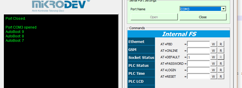
When the device is restored to factory settings, the settings made with the AT commands are restored to factory settings, the most recently loaded Mikrodiagram project is deleted from the device.
After the command is sent, the device drops to error ERROR =61.
The command AT+DEFAULT is only writable.
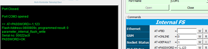
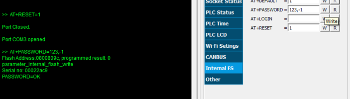
AT+PASSWORD
•Add Password
AT+PASSWORD= -1,"PASSWORD"
- AT+LOGIN
AT+LOGIN=0 --- If the device has a password defined.
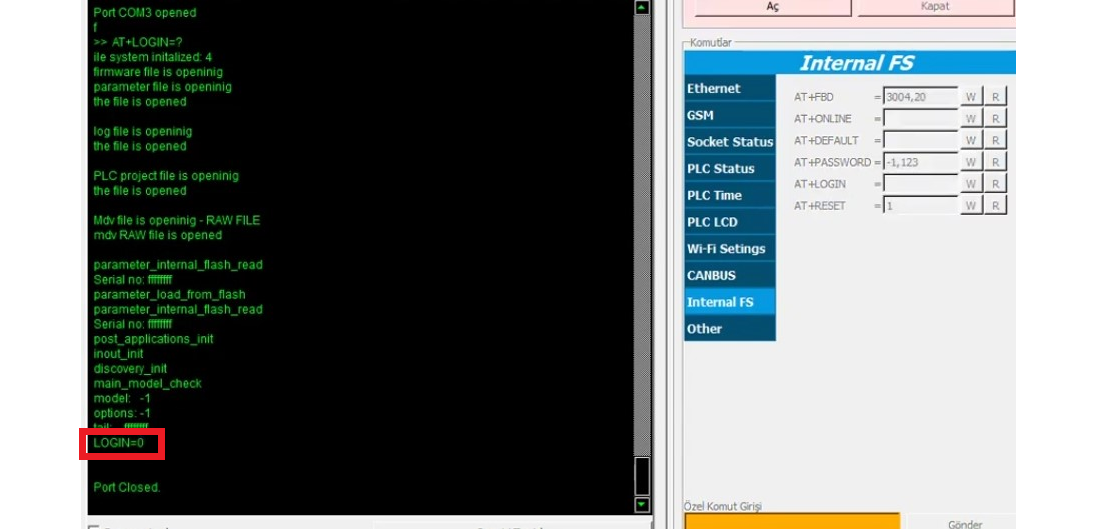
AT+LOGIN=1 --- If no password is defined on the device
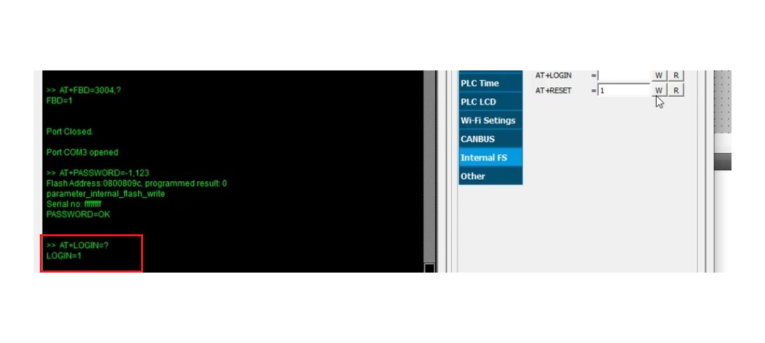
- AT+RESET
The AT + RESET command is used for software restart of the device.
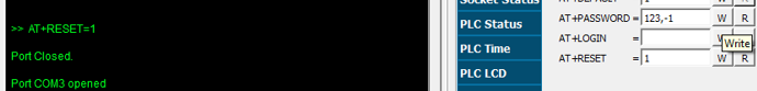
When AT + RESET = 1 is typed and the "send" button is clicked, the device is restarted.
Other
- AT+ADCERROR
ADC (Analog to Digital Converter). With this command the count of ADC errors is learned.

- AT+FORMATFS
The AT+FORMATFS =1 command is used to format Mikrodev products. While the device is counting "autoboot", sending the AT + FORMATFS = 1 command to the device will delete the firmware, so it is necessary to reload the firmware to program the device.
Other AT Commands
- AT+GSMRESET
The AT+GSMRESET command is queried by writing it from the Custom Command Input section.
If the device can't establish a GSM connection with in the time specified with the AT+GSMRESET command, it resets.

- AT+TEMPTYPE
Adjustments are made for the RTD temperature sensor.
- AT+TEMPTYPE=0 --- RTD Close
- AT+TEMPTYPE=2 --- RTD Open
In order to make these adjustments, the device must have an RTD temperature sensor.
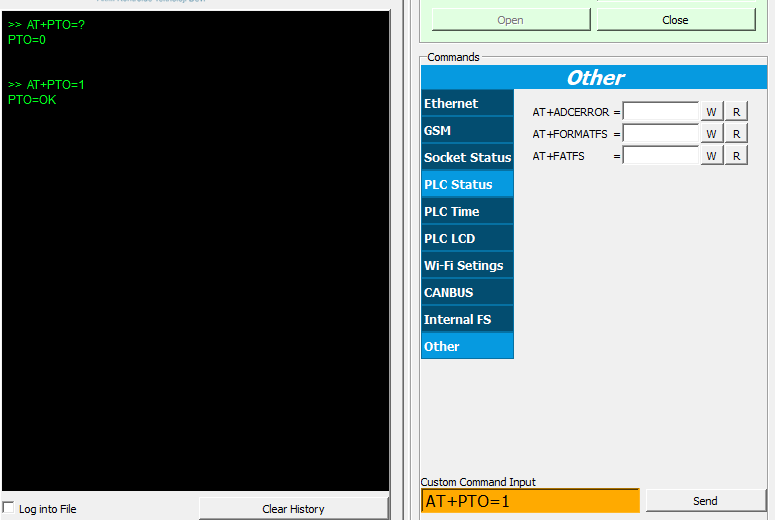
- AT+PTO
It is used to activate the "pulse train output" and "axis control" blocks.
- AT+PTO =1 command is activated.
- AT+PTO =0 disable the command.
For current status inquiry, "AT + PTO =?" Command can be sent.
- AT+PROTOCOLMAP
Queries the OBIS Codes installed on the device.
- AT+MIKRODEV
The AT+MIKRODEV command is queried by writing it from the Custom Command Input section.
With the AT+MIKRODEV command, the serial number of the device is learned.
"AT+MIKRODEV=?" format is used.
- AT+SOFTRESET
The AT+SOFTRESET command is queried by writing it from the Custom Command Input section.
With the AT+SOFTRESET command, the reason for the last reset of the device is learned.
| AT+SOFTRESET =? | DESCRIPTION |
|---|---|
| pin reset | The NRST pin has been reset by pulling low. If you have this next to other resets, don't pay attention to it |
| POR/PDR reset | Power Down Reset, the power of the device has been cut, therefore it has been reset |
| Software Reset | Caused by AT+RESET=1 or AT+PLCRESET parameter, the device has reset itself on purpose |
| Independent Watchdog reset | The software was locked, so the watchdog timer reset to recover the device |
| Window Watchdog reset | The software was locked, so the watchdog timer reset to recover the device |
| Low Power reset | The supply level of the device has fallen below the acceptable threshold. So the devices was reset |
Sending AT Commands With SMS
You can get and change the data in PLC by sending AT commands from a mobile phone. The following shows sample applications and the transmission of several AT commands.
To enable SMS Console;
To set a string via SMS: Send SMS text message to device in following format:
AT+FBD= < Block No >, NewTextValue
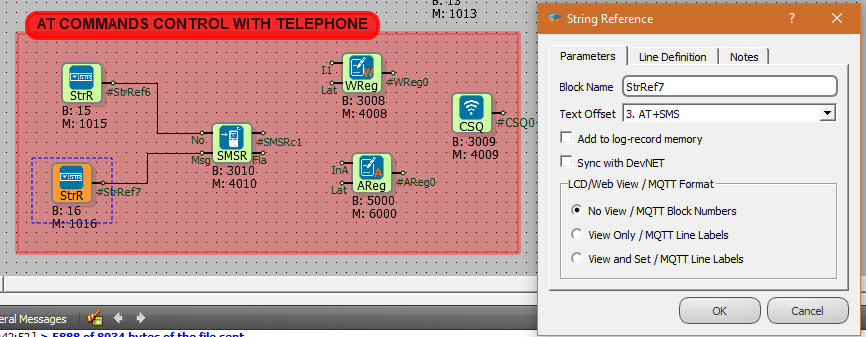
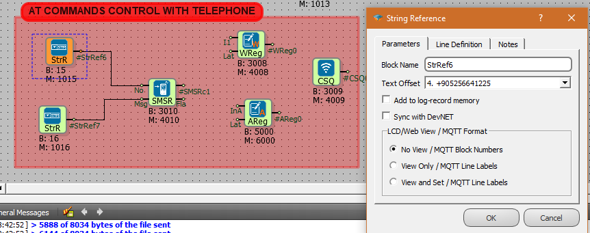
In order to update String Text referenced by String refeecne block (Block No: 15) and String Text Offset 4, send a SMS to device like follows:
AT+FBD=15,+905256641225
Send above SMS text message to the device, to change a string referecence value from remote
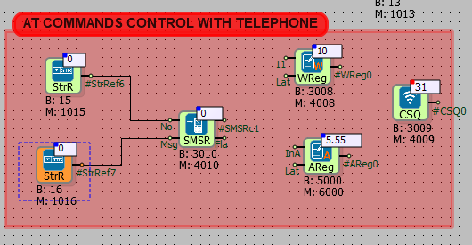
To enable SMS console, select the String Reference Text Offset "AT + SMS" to the SMSR Msj input. Word Register and Analog Register value is 0.
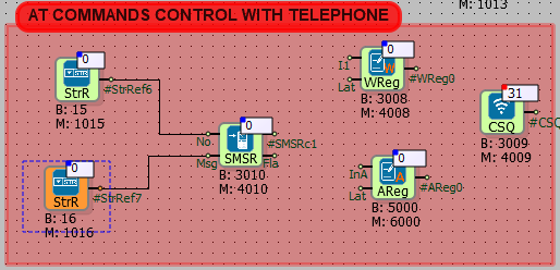
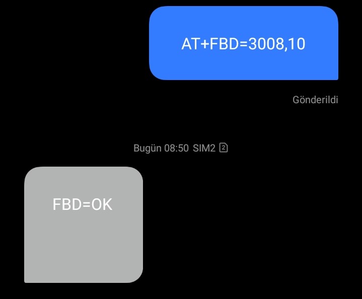
To change the value in the word register, AT+FBD =3008,10 is sent from Mobil.Word Register value is 10.
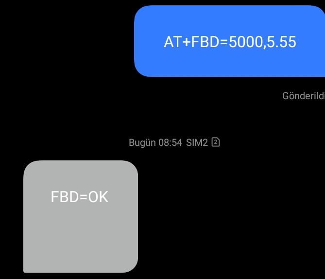
To change the value in the analog register, AT+FBD =5000,5.55 is sent from Mobil.Analog Register value is 5.55.
The following table shows the sending and incoming responses of AT commands from the mobile.