DNP3 SLAVE Application Notes
DNP3 SLAVE
General Information
DNP3 protocol is a distributed communication protocol. Primary advantage are:
•Time-labeled variable support
•Ability to re-send the events that occurred during the absence of communication when connected with the time tags.
•The ability of SCADA to automatically send changes without the need to query.
•Ability to query multiple variables as a class, not individually
•Time syncronization
DNP3 SLAVE Driver
Mikrodev RTU devices are supports DNP3 SLAVE mode and gives service to DNP3 supported systems over TCP IP and/or SerialPort . The following services are supported:
1- Bulk object reading with Class object query
2- Time syncronization
3- Event control in instantaneous measurement data as a percentage and level
4- Automatic send the event datas
5- Periodically send the points of data
DNP3 Slave Block Definitions
Connections
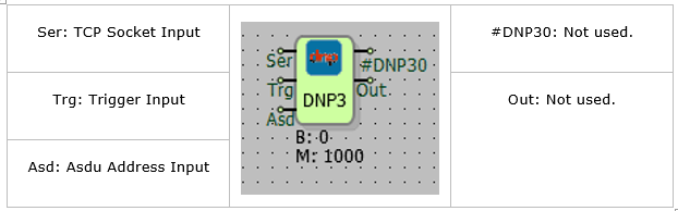
Connection Explanation
Ser: TCP Socket Input
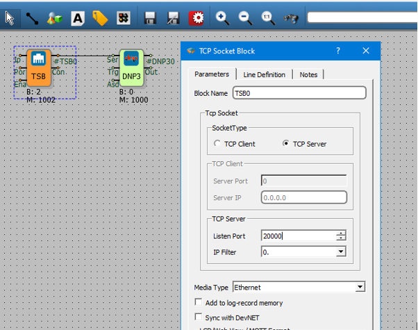
The TCP server socket block, where the DNP3 protocol will run, is connected from this input.
Trg: Trigger Input
The trigger input for periodically send operation. Works as a rising edge.
Asd: Asdu Address Input
It is used as an ASDU address entry.
Block Explanation
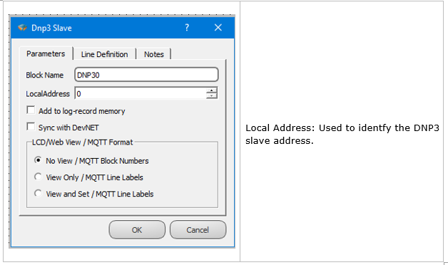
By adding the DNP3 slave block, DNP3 is activated on the RTU. TCP or Seriport block is added to the DNP3 block Ser entry. To serve more than one server, a DNP3 block must be added for each server. If the DNP3 asdu address is to be set from outside the ASD entry is used.On the rising edge of trigger , periodic submission between DNP3 objects active selected objects, send to server with periodic COT. The input of trigger and can be left blank.
DNP3 Variable Table Definitions
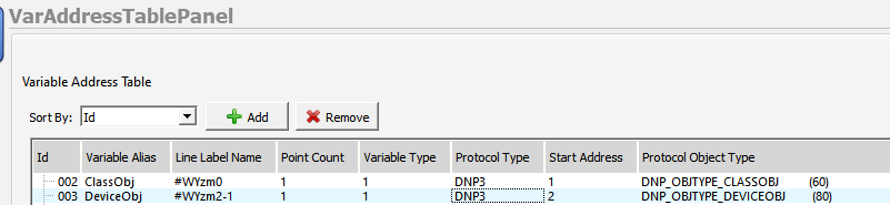
Variable Table
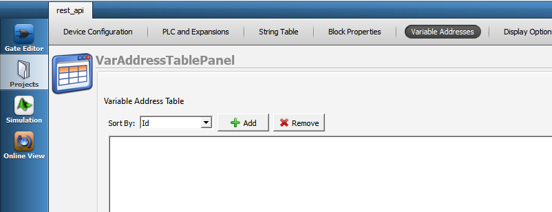
To RTU logic project , Dnp3 becomes active in the DNP3 protocol within the RTU with the addition of the Slave Block to DNP3. Variables that in the RTU logic, The association of DNP3 is provided in the variable address table.
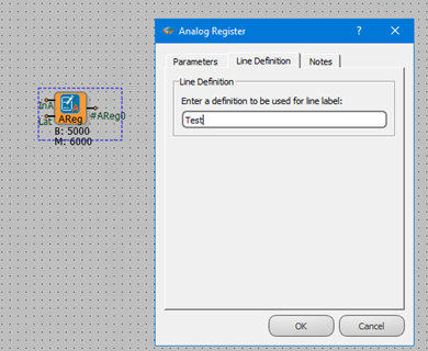
Line Label Definition
Line label can be defined for all blocks defined on the microdiagram. In order to associate with the protocol addresses in the variable table, the line label must be defined.
Line Label Attribution
Associating the protocol adresses with line labelss, The variable is provided from the menu by pressing the “Add” button in the address table.
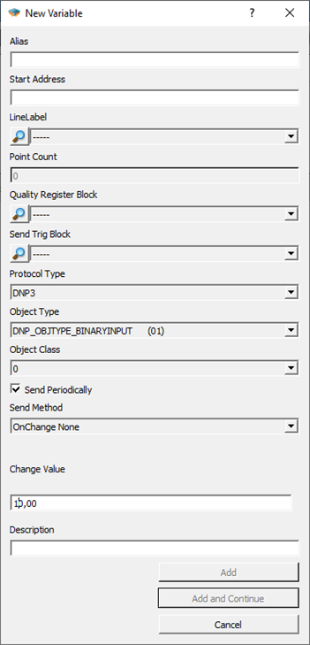
Alias:
A special name is given that defines this variable.
Start Address:
The address reserved for this variable on SCADA is written here.İt is written as a Decimal value.
LineLabel:
The block to be associated with on the microdiagram is selected by the line label.
Point Coint:
It is calculated automatically. It makes sense in tables.
Protocol Type:
Modbus, Dnp3, iec101, iec104 to choosing from among them. The Object Type will change according to the protocol type.
Object Type:
DNP3 object type information is selected. See protocol type information for detailed information.
Object Class:
The class information to which the variable belongs is selected.
Send On Trigger:
When Dnp3 Slave is detected from the trigger input in the trigger block, it is the choice of whether to send this variable as a periodic send to SCADA.
Send Method:
When the value of the defined variable changes, the operation to be performed is selected.
None: Spinner does not trigger submission.
Level: When the amount defined "Change Value" changes, sending is triggered.
Percentage: Submission is triggered when there is a percentage change defined in " Change Value”.
Change Value:
Sets the percent or level change value with” Send method".
DNP3 Object Types
DNP3 Object Types in Reading Direction
| DNP3 Object Type | Register Data Type |
|---|---|
| Single Bit Binary Input : Data Object 01 - Variation 01 | Binary, Word, Analog, Long |
| Binary Input With Status :Data Object 01 - Variation 02 | Binary, Word, Analog, Long |
| Binary Input Change Without Time : Data Object 02 - Variation 01 | Binary, Word, Analog, Long |
| Binary Output : Data object 10 - Variation 01 | Binary, Word, Analog, Long |
| Binary Output Status : Data object 10 - Variation 02 | Binary, Word, Analog, Long |
| 32 BIT Analog Input : Data Object 30 - Variation 01 | Long |
| 16 BIT Analog Input : Data Object 30 - Variation 02 | Binary, Word |
| 32 BIT Analog Input Without Flag : Data Object 30 - Variation 03 | Long |
| 16 BIT Analog Input Without Flag : Data Object 30 - Variation 04 | Binary, Word |
| Short Float Analog Input Without Flag : Data Object 30 - Variation 05 | Analog |
NOTE 1: A variable of type DNP_OBJTYPE_CLASSOBJ must be added from the variable Adress table to draw Class 0, Class 1, and Class 2 data. Other settings of this variable, such as address, line tag, can be selected at random.
DNP3 Object Types in Control Direction
The write variable is also automatically generated for each block mapped to the read type. The types of variables that can be accessed as write to defined read objects are as follows:
| DNP3 Object Type | Register Data Type |
|---|---|
| Control Relay Output Block : Data Object 12 - Variation 01 | Binary, Word, Analog, Long |
| 32 Bit Analog Output Block : Data Object 41 - Variation 01 | Long |
| 16 Bit Analog Output Block : Data Object 41 - Variation 02 | Binary, Word |
| Short Float Analog Output Block : Data Object 41 - Variation 03 | Analog |
DNP3 Event Mechanism
Event Definition for DNP3 Objects
In the variable address table, the send in change selection is available for DNP3 objects. When the value of the variable defined in this menu changes, the operation to be performed is selected.
None: Spinner does not trigger submission
● Level: when the amount defined in “Change Value” is changed, the sending is triggered.
● Percentage: Submission is triggered when there is a percentage change defined in " Change Value”.
The change face or level is set with the value” Change Value". Sets the percent or level change value with “Send method”.
DNP3 Instantaneous Transmission of Event Situations
The RTU device tags the states defined as send and change detected as events and assigns a time tag to the event. In case of a tagged event, if there is a connection to the server and the server is active in the device sending “UNSOLICED”, the relevant object is immediately forwarded as “UNSOLICED”.
If the connection exists with the server and the events detected with the “UNSOLICITED” sending active are sent with the DNP3 object types specified in the following table.
| DNP3 Object Type | Register Data Type |
|---|---|
| Binary Input Change Without Time : Data Object 02 - Variation 01 | Binary |
| 32 Bit Analog Input Change Without Time : Data Object 32 - Variation 01 | Long |
| 16 Bit Analog Input Change Without Time : Data Object 32 - Variation 02 | Word |
| Short Float Analog Input Change Without Time : Data Object 32 - Variation 05 | Analog |
DNP3 Time-Tagged Submission Of Event States
Event Controls continue passively sending “UNSOLICED” even if there is connection to the server or even if there is no connection. In the event of an event under these circumstances, event information is recorded in the event memory with the time tag and this data is kept in the device as CLASS 1 data. This event data stored in memory can be read by the server with Class 1 data read management. This CLASS 1 data is also automatically forwarded to the server by RTU if” UNSOLICED " sending is enabled.
Class 1 event data is dispatched with the DNP3 object types specified in the following table.
| DNP3 Object Type | Register Data Type |
|---|---|
| Binary Input Change With Time : Data Object 02 - Variation 02 | Binary |
| 32 Bit Analog Input Change With Time : Data Object 32 - Variation 03 | Long |
| 16 Bit Analog Input Change With Time : Data Object 32 - Variation 04 | Word |
| Short Float Analog Input Change With Time : Data Object 32 - Variation 07 | Analog |