IEC104 Application Notes
General Information
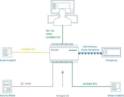
The IEC 60870-5-104 protocol is a widely used distributed communication protocol. The main advantages of the IEC104 protocol are:
• Time stamped variable support
• Ability to resend events that occur when there is no communication, when a connection is established with time stamps.
• Ability to send changes automatically without the need for SCADA to query.
• Ability to query variables not individually, but multiple as a class.
IEC 60870-5-104 Slave Driver
Mikrodev RTU devices support IEC 60870-5-104 SLAVE mode and serve SCADA systems supporting IEC 60870-5-104 over TCP/IP. The following services are supported:
Reading all data points with General Interrogation query
Time synchronization
Event control on instant measurement data as percentage and level
Automatic sending of defined Event data (Case of Transmission, Spontaneous 0x03)
Periodic sending of data points (Case of Transmission, Periodic 0x01)
Storing the event information and sending it again when communication is established
Execution Mode support in sending commands; Execute Only, Select Before Execute, Long Pulse, and Short Pulse Duration support sending Quality Descriptor information.
Ability to open more than one Slave and define different IEC104 objects for each Slave.
IEC 104 Slave Block Definitions
Connections
Connection Explanations
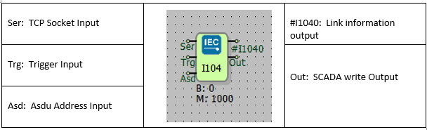
Ser: TCP Socket Input.
The TCP server socket block from which the IEC104 protocol will work is connected from this input
Trg: Trigger Input
Trigger input for periodic sending. It works as a rising edge.
Asd: Asdu Address Input
The ASDU address is used as input.
#I104: Connection Status Output
If the IEC104 connection between SCADA and RTU is installed, this output value is 1, otherwise 0.
Block Settings
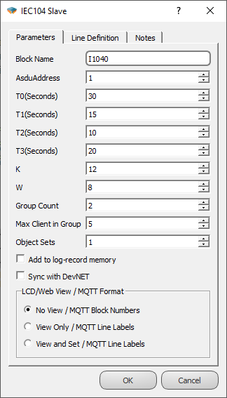
AsduAddress: The ASDU address of the IEC104 Slave Block can be defined from this section or from the ASDU input of the IEC104 Slave block.
T0: TCP connection timeout period.
T1: Test APDU timeout period.
T2: Timeout period for Ack.
T3: Test frame sending time.
K: The maximum allowable difference between the sequence number in the received packet and the number in the send status variable.
W: ACK is sent after receiving W up to I Format APDU.
Group Count**: The number of Masters that the device can establish connections with as an IEC 104 Slave is specified here. This value can be a maximum of 2 for RTU devices and a maximum of 4 for DM devices.
Max Client in Group**: The maximum number of Slave connections that can be established to an IEC 104 Master is specified here. (Currently set to 5.)
Object Sets*: It is used to define multiple IEC 104 Slaves. Thanks to the value entered here, IEC 104 objects can be assigned to different Slave addresses. It is used in conjunction with the 'Object Set No' in the Variable Address Table. For more detailed information, please refer to the Block Descriptions.
Add to log-record memory: If block values are desired to be added to the event log memory when there is no connection with the server, the "Add to Log Memory" option should be selected.
Sync with DevNET: If it is desired to send the values of all blocks to the server when the connection is established, this option should be selected.
*This is valid for Telediagram version 18 and later.
**In Telediagram versions earlier than 18, these features are provided by sending special commands through the Mikroterminal application.
Block Information
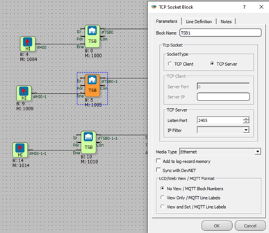
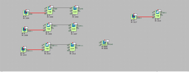
To enable the IEC104 protocol over RTU, you need to add an IEC104 Slave block to the Telediagram project and connect the TCP Socket block to the "Ser" input of the IEC104 Slave block. In the TCP Socket block settings, the TCP Socket Type should be selected as "Server" and the listening port should be defined. To activate the TCP Socket block, the "Ena" input of the TCP Socket block should be connected to the High Gate block.
If you want to serve multiple servers, you need to add an IEC104 Slave block for each server in the Telediagram project.
The IEC104 ASDU address can be configured either from the block settings of the IEC104 Slave block or from the "Asd" input of the IEC104 Slave block.
The values of the IEC104 objects that are selected for periodic transmission will be sent to the server when a rising edge signal is received at the "Trg" input of the IEC104 Slave block. If there is no data transmission through periodic or trigger-based methods, the trigger input can be left unconnected.
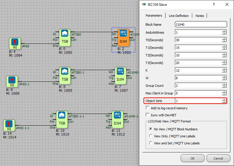
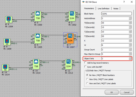
If you want to open multiple IEC104 Slaves on the device, you should make the configuration from the "object sets" section in the block settings of the IEC104 Slave block. This section is used in conjunction with the variable address table. When defining IEC104 objects in the variable address table, the "object set no" entered should correspond to the object sets value.
For example, if the "object sets" value in the block settings of the IEC104 Slave block is set to 1, the "object set no" in the variable address table should be 0. (2^0=1)
If the "object sets" value is set to 2, the "object set no" in the variable address table should be 1. (2^1=2)
And if the "object sets" value is set to 8, the "object set no" in the variable address table should be 3. (2^3=8)
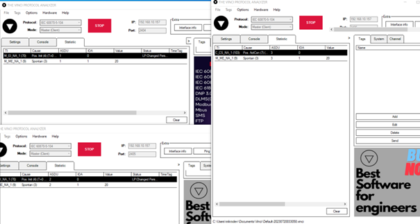
Sample Application
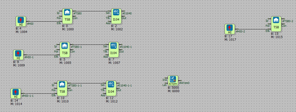
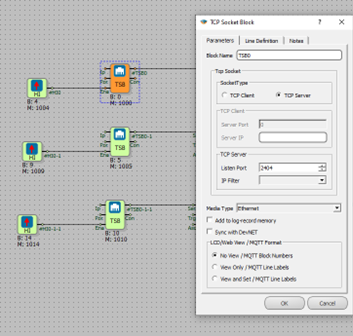
In the example application, three different IEC104 Slave blocks were defined for three different listening ports. During the configuration, each IEC104 Slave block was assigned a different "Object Sets" value.
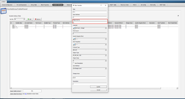
For listening port 2404, the "Object Sets" value of the IEC104 Slave block is specified as 1 in the block settings. Therefore, the corresponding "Object Set No" value in the variable address table is entered as 0. (2^0=1)
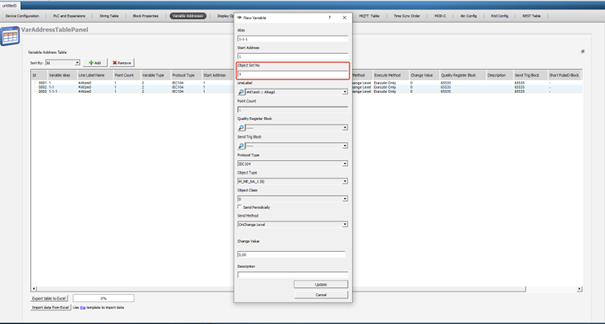
For listening port 2405, the "Object Sets" value of the IEC104 Slave block is specified as 2 in the block settings. Therefore, the corresponding "Object Set No" value in the variable address table is entered as 1. (2^1=2)
For listening port 2406, the "Object Sets" value of the IEC104 Slave block is specified as 8 in the block settings. Therefore, the corresponding "Object Set No" value in the variable address table is entered as 3. (2^3=8)
IEC 104 objects have been defined in the variable address table. A TCP connection has been established to the device, and online monitoring has been initiated.
IEC104 Masters were opened for different listening ports through the Vinci application, and the transmitted values were monitored.
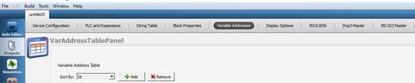
IEC104 Variable Address Table Definitions
Variable Address Table
With the addition of the IEC104 Slave Block to the Telediagram project, the IEC104 protocol becomes active within the RTU.
The association of variables with IEC104 is provided through the variable address table in the Telediagram project.
Defining Line Labels
In the Telediagram software, automatic line label is provided for all blocks added to the Telediagram project. To facilitate project readability, line label can be done based on the usage locations of the blocks.
Note: When defining line label, ensure not to leave any spaces and avoid using Turkish characters.
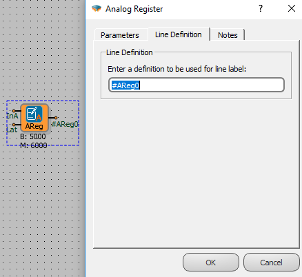
Attaching a Line Label
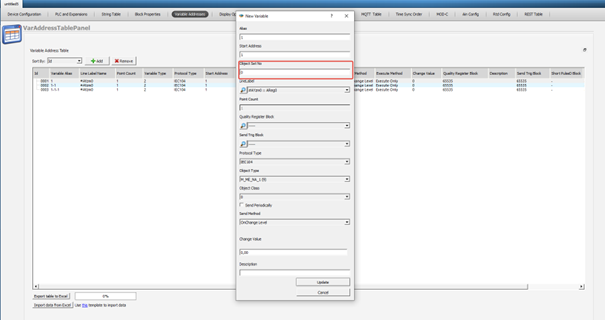
Associating protocol tags with line labels, variable address is provided from the menu by pressing "Add" button in the address table.
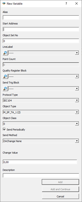
Alias: A special name is given that defines this defined variable.
Start Address: The address allocated for this variable on SCADA is written here. It is written as a decimal value.
Object Set No: It is used to define multiple IEC104 Slaves. Through this value, IEC104 objects can be assigned to different Slave addresses. It is used in conjunction with the "Object Sets" section in the block settings of the IEC104 Slave block. For detailed information, please refer to the "Block Descriptions" section.
Line Label: The block to be associated on the Telediagram is selected with the line label.
Point Count: Calculated automatically. It makes sense on tables.
Quality Register Block: Block entry to define Quality Register. For detailed information, please refer to the "Quality Register Block Settings" section.
Send Trig Block: If you want to send IEC104 data with an independent trigger from the trigger input of the block, the trigger block is selected from this section and the periodic send option in the block special settings must not be ticked in order to send trigger-dependent data here.
Protocol Type: Modbus, Dnp3, IEC101, IEC104 are selected. Object type will change according to protocol type.
Object Type: IEC104 object type information selected. For detailed information, please refer to the "Object Types" section.
Object Class: The class information to which the variable belongs is selected.
Send Periodically: It is the selection of whether to send periodic sending to SCADA in this variable when the trigger is detected from the Trigger input on the IEC104 Slave block.
Send Method: If the value of the defined variable is changed, the operation to be performed is selected.
On Change None: The spin submission is not triggered.
On Change Level: When the amount defined in "Change Value" changes, sending is triggered.
On Change Percentage: Sending is triggered when there is a change in the percentage defined in "Change Value".
On Change Integral: If the accumulated change of the added object within the unit time, defined by the "Change Value," exceeds, the transmission is triggered. The unit is in seconds. For detailed information, please refer to the "IEC104 Event Mechanism" section.
Change Value: Sets the percentage or level change value together with the "Send method".
Description: It is the description input.
IEC104 Object Types
IEC104 Read Direction Object Types
| IEC104 Object | Pe |
|---|---|
| 1 (single-point) | Binary, Word, Analog, Long |
| 3 (double-point) | Word, Analog, Long |
| 5 (step position) | - |
| 7 (bitstring) | - |
| 9 (measured normalized value) | Binary, Word, Analog, Long |
| 11 (measured scaled value) | - |
| 13 (measured short floating point) | Binary, Word, Analog, Long |
| 15 (integrated totals) | - |
| 20 (packed single-point) | - |
| 21 (normalized value without quality descriptor) | - |
| 30 (single-point information with time tag) | Binary, Word, Analog, Long |
| 31 (double-point information with time tag) | Word, Analog, Long |
| 32 (step position information with time tag) | - |
| 33 (bitstring of 32 bit with time tag) | - |
| 34 (measured normalized value with time tag) | Binary, Word, Analog, Long |
| 35 (measured scaled value with time tag) | - |
| 36 (measured short floating point number with time tag) | Binary, Word, Analog, Long |
| 37 (integrated totals with time tag) | - |
| 38 (event of protection equipment with time tag) | - |
IEC104 Object Types in Control Direction
The write variable is also automatically created for each block matched with the read type. Variable types that can be accessed as writing to defined read objects are as follows:
| Selected for a reading - IEC104 Object Types | IEC104 Object Types - That can be accessed for writing to the same data point |
|---|---|
| 1 (single-point) | 45 (single command), 58 (single command with time tag) |
| 3 (double-point) | 46 (double command), 59 (double command with time tag) |
| 13 (measured short floating point) | 50 (set point command, short floating point), 63 (set point command, short floating - point number with time tag |
| 30 (single-point information with time tag) | 45 (single command), 58 (single command with time tag) |
| 31 (double-point information with time tag) | 46 (double command), 59 (double command with time tag) |
| 36 (measured short floating point number with time tag) | 50 (set point command, short floating point), 63 (set point command, short floating - point number with time tag) |
Quality Register Block Settings
Quality Descriptor (QDS) bits and accordingly Quality Register Block Settings are supported in our devices. Quality Descriptor bit definitions; OV, BL, SB, NT, IV, CY, CA, EI. As it is known, the use of QDS varies according to the defined object types. The Quality Descriptor (QDS) identification table is shown below.
| Status / QDS | OV | CY | CA | EI | BL | SB | NT | IV |
|---|---|---|---|---|---|---|---|---|
| overflow quality flag | carry flag | adjusted flag | blocked quality flag | substituted quality flag | topical quality flag | invalid quality flag | ||
| 1 | overflow | carry | counter was adjusted | elapsed time not valid | blocked | substituted | not topical | invalid |
| 0 | no overflow | bo carry | counter was not adjusted | elapsed time valid | not blocked | not substituted | topical | valid |
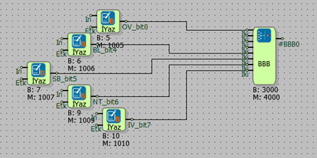
The QDS values to be used are created with the Bit Combination Block and defined by the Quality Register Block setting during the IEC 104 association in the variable addresses section.
For example, we will define the reading value with the IEC 104 protocol. We select 36 – measured short floating point number with time tag, as the reading object type. We will define QDS values for Quality Register Block definition. For this, the QDS bit definition is as follows; It should contain 0.bit OV, 4.bit BL, 5.bit SB, 6.bit NT, 7.bit IV. We can define Bit Combining Block as Quality Register Block.
Command Send Settings
It supports Single Command, Double Command and Set Point Command for appropriate object types in IEC 104 protocol. Object types command types mapping is shown in the Object Types Table. The settings are as follows; Depending on the object type, the options appear automatically in the selected IEC 104 protocol settings during line label association.
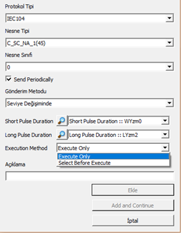
For example, when Object type 45 (Single Command) is selected, options for parameter settings become active as seen in Figure 2. A register is selected for either Short Pulse Duration or Long Pulse Duration values. It should be noted that the entered value will be treated as ms.
The Execution Method is also selected from the list. The Execution Method is of 2 types. Execute Only is selected if the operation is desired to be performed with a single command. If 2 different confirmation states are desired, Select Before Execute is selected.
For example, the Select Before Execute option can be used for transactions that require confirmation with 2 different commands. For this, the Select command must be sent first and then the Execute command.
IEC 104 Event Mechanism
The variable address table has a send on exchange selection for IEC 104 objects. The selection of the action to be taken when the value of the variable defined in the variable address table changes is determined by the send method defined in the variable address table. The send method is used in conjunction with the change value section.
On Change None: The spin submission is not triggered.
On Change Level: When the amount defined in "Change Value" changes, the sending is triggered.
On Change Percentage: Sending is triggered when there is a change in the percentage defined in "Change Value".
On Change Integral: If the accumulated change of the added object within the unit time, defined by the "Change Value," exceeds, the transmission is triggered.
The "Change Value" in conjunction with the "Send Method" sets the percentage, level, and integral change value.
For example, if the send method for the IEC104 object defined in the variable address table is set to "Integral Change" and the change value is set to 10:
When the change amount of the defined variable is 2 (the difference between the current value and the previous value of the defined variable), the transmission will be triggered after 5 seconds (10 divided by 2, based on the change value entered in the variable address table).
When the change amount of the defined variable is 5, the transmission will be triggered after 2 seconds (10 divided by 5).
When the change amount of the defined variable is 15, the transmission will be triggered immediately as it exceeds the change value entered in the variable address table.
The RTU device tags the statuses that are send on change and change detected as events and assigns a time tag to the event. In case of a tagged event, if there is a connection with the server, the relevant object is transmitted immediately as COT 0x03 Spontaneous.
If there is no connection with the server, the device is added to the event log memory and stored for sending when the server connection is established again. For storage, the option "Add to log-record memory" must be selected in the IEC104 Slave block settings.
Note: If all tags are to be sent to the server when the connection is established, the Sync with DevNET option must be selected in the IEC104 Slave block settings.
Note: The values of selected objects with periodic sending between IEC104 objects are not detected as events. That is, periodic submissions are not added to the log memory when there is no connection.
IEC104 Redundancy Group Specification
Note: The settings described below are valid for Telediagram version before 18.
For version 18 and later, the adjustments are made through the block settings of the IEC104 Slave Block in Mikroterminal.
Mikrodev RTU can connect with IEC 104 Master as IEC 104 Slave. The number of Master IPs to be connected to this must be defined to the device with the AT command and via the IEC104 Slave block.
For Telediagram version before 18:
The Mikroterminal application opens, from the special command entry section.
The command AT+OPTIONS=7,< NUMBER OF MASTER IP TO CONNECT > is sent.
For example, if Edaş has two different server IPs, this command would be as follows:
AT+OPTIONS=7,2
AT+OPTIONS=7,2 Write Commad OPTIONS=OK
AT+OPTIONS=7,? Read Command OPTIONS=2
After entering this parameter, the device must be reset. AT+RESET=1
Note: The maximum number of Masters that the IEC104 Slave block can connect to is 2 for RTU series devices and 4 for DM series devices.
For Telediagram version 18 and later, please refer to the "Block Settings" section for Redundancy Group definition.
Ability to Edit the Analog Threshold Value Retained in the Log Recording Memory
While there is no connection, changes can be made on the threshold values of the analog values kept in the log memory.
The Mikroterminal application opens, will be sent from the custom command line
AT+OPTION=8,< ANALOG EVENT MULTIPLIER >
Analog event multiplier on the command line, analog log recorded when there is no connection, it allows to operate on the threshold values of the values. Values written here are from 0 if set differently, when there is no connection, the event threshold is multiplied by the coefficient here.
For example;
If AT+OPTION=8.0, analog events are not added to the log memory if there is no connection.
If AT+OPTION=8.1, it records the change in the log memory as much as the value entered in the variable table.
If AT+OPTION=8.10, a change that is 10 times larger than the value entered in the variable table will also be recorded in the log memory.
AT+OPTIONS=8,10 Write Command
OPTIONS=OK
AT+OPTIONS=8,? Read Command
OPTIONS=10
After entering this parameter, the device must be reset. AT+RESET=1
Note: The threshold value entered here applies to all defined IEC104 Slaves in the project.
IEC104 Connection Information Learning Command
IEC104 connection information can be learned with AT command.
For Telediagram version before 18:
The Mikroterminal application opens, from the custom command input.
The command AT+COMSTATUS=iec104 is sent.
IEC104 redundancy group number =2 command query example when there is no selected connection;
AT+COMSTATUS=iec104
IEC104 CLIENT GROUP[0]:00000000
isDataTransStarted:0
NumofActiveConnections:0
MaxNumberOfEvents:256
RefInstance:200111b8
EventItems:1000c800
ObjMap:10005ab0
connection[0]:00000000
connection[1]:00000000
connection[2]:00000000
connection[3]:00000000
connection[4]:00000000
IEC104 CLIENT GROUP[1]:00000000
isDataTransStarted:0
NumofActiveConnections:0
MaxNumberOfEvents:256
RefInstance:200115f8
EventItems:1000dc00
ObjMap:100064f4
connection[0]:00000000
connection[1]:00000000
connection[2]:00000000
connection[3]:00000000
connection[4]:00000000
COMSTATUS=
IEC104 redundancy group number =2 selected, command query example when there is only one connection;
AT+COMSTATUS=iec104
IEC104 CLIENT GROUP[0]:4d0aa8c0
isDataTransStarted:1
NumofActiveConnections:1
MaxNumberOfEvents:256
RefInstance:2000f4c8
EventItems:1000c800
ObjMap:1000518c
connection[0]:20010b30
DataTransStarted: 1
connection[1]:00000000
connection[2]:00000000
connection[3]:00000000
connection[4]:00000000
IEC104 CLIENT GROUP[1]:00000000
isDataTransStarted:0
NumofActiveConnections:0
MaxNumberOfEvents:256
RefInstance:2000f908
EventItems:1000dc00
ObjMap:100052ac
connection[0]:00000000
connection[1]:00000000
connection[2]:00000000
connection[3]:00000000
connection[4]:00000000
COMSTATUS=
For Telediagram version 18 and later:
The Mikroterminal application opens, from the custom command input.
The command AT+COMSTATUS=iec104,< block number > is sent.
The block number specified on the command line is the block number of the IEC104 Slave block from which the connection information is to be retrieved.
IEC104 redundancy group number =2 command query example when there is no selected connection;
AT+COMSTATUS=iec104,2
IEC104 CLIENT GROUP[0]:d20aa8c0
isDataTransStarted:0
NumofActiveConnections:0
MaxNumberOfEvents:85
RefInstance:200100d0
EventItems:1000c800
ObjMap:10005134
connection[0]:00000000
connection[1]:00000000
connection[2]:00000000
connection[3]:00000000
connection[4]:00000000
IEC104 CLIENT GROUP[1]:390aa8c0
isDataTransStarted:0
NumofActiveConnections:0
MaxNumberOfEvents:85
RefInstance:20010518
EventItems:1000cea4
ObjMap:1000518c
connection[0]:00000000
connection[1]:00000000
connection[2]:00000000
connection[3]:00000000
connection[4]:00000000
COMSTATUS=
IEC104 redundancy group number =2 selected, command query example when there is only one connection;
AT+COMSTATUS=iec104,2
IEC104 CLIENT GROUP[0]:d20aa8c0
isDataTransStarted:1
NumofActiveConnections:1
MaxNumberOfEvents:85
RefInstance:200100d0
EventItems:1000c800
ObjMap:10005134
connection[0]:20012bc0
DataTransStarted: 1
connection[1]:00000000
connection[2]:00000000
connection[3]:00000000
connection[4]:00000000
IEC104 CLIENT GROUP[1]:390aa8c0
isDataTransStarted:0
NumofActiveConnections:0
MaxNumberOfEvents:85
RefInstance:20010518
EventItems:1000cea4
ObjMap:1000518c
connection[0]:00000000
connection[1]:00000000
connection[2]:00000000
connection[3]:00000000
connection[4]:00000000
COMSTATUS=
Command to Learn IEC104 Master IPs Connected to TCP Socket Block
With AT command, IEC104 Master IPs connected to TCP Socket block can be learned.
The Mikroterminal application is opened, from the special command entry or from the command line that says AT+STATUS= in the Socket Status section.
The AT+SOCKET=< TCP Socket Block Number > command is sent.
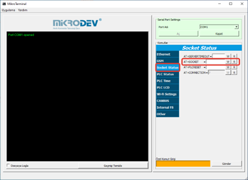
Example of IEC104 Master IP Query connected to TCP Socket block with 4 block numbers;
AT+SOCKET=4
Ip: 172.21.1.1, Port: 65063, Status: 2
Ip: 172.21.1.1, Port: 65514, Status: 3
Ip: 172.21.1.2, Port: 46076, Status: 2
Ip: 172.21.1.2, Port: 45799, Status: 2
AT+COMSTATUS=iec104
IEC104 CLIENT GROUP[0]:020115ac
isDataTransStarted:1
NumofActiveConnections:2
MaxNumberOfEvents:256
RefInstance:200110b0
EventItems:1000c800
ObjMap:10005ab0
connection[0]:20014b78
DataTransStarted: 1
connection[1]:00000000
connection[2]:20013430
DataTransStarted: 0
connection[3]:00000000
connection[4]:00000000
IEC104 CLIENT GROUP[1]:010115ac
isDataTransStarted:1
NumofActiveConnections:2
MaxNumberOfEvents:256
RefInstance:200114f0
EventItems:1000c900
ObjMap:100064f4
connection[0]:20013838
DataTransStarted: 0
connection[1]:00000000
connection[2]:20014770
DataTransStarted: 1
connection[3]:00000000
connection[4]:00000000
COMSTATUS=