Telediagram Editor
Using IEC 104
General Information
The IEC 60870-5-104 protocol is a widely used distributed communication protocol. The main advantages of the IEC104 protocol are:
• Time stamped variable support
• Ability to resend events that occur when there is no communication, when a connection is established with time stamps.
• Ability to send changes automatically without the need for SCADA to query.
• Ability to query variables not individually, but multiple as a class.
IEC 60870-5-104 Slave Driver
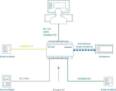
Mikrodev RTU devices support IEC 60870-5-104 SLAVE mode and serve SCADA systems supporting IEC 60870-5-104 over TCP/IP. The following services are supported:
Reading all data points with General Interrogation query
Time synchronization
Event control on instant measurement data as percentage and level
Automatic sending of defined Event data (Case of Transmission, Spontaneous 0x03)
Periodic sending of data points (Case of Transmission, Periodic 0x01)
Storing the event information and sending it again when communication is established
Execution Mode support in sending commands; Execute Only, Select Before Execute, Long Pulse, and Short Pulse Duration support sending Quality Descriptor information.
Ability to open more than one Slave and define different IEC104 objects for each Slave.
IEC 104 Slave Block Definitions
Connections
Connection Explanations
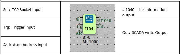
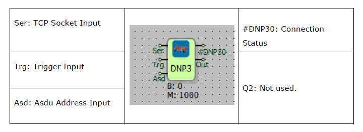
Ser: TCP Socket Input.
The TCP server socket block from which the IEC104 protocol will work is connected from this input
Trg: Trigger Input
Trigger input for periodic sending. It works as a rising edge.
Asd: Asdu Address Input
The ASDU address is used as input.
#I104: Connection Status Output
If the IEC104 connection between SCADA and RTU is installed, this output value is 1, otherwise 0.
Block Settings
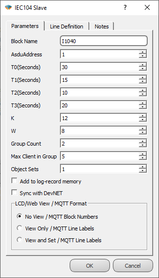
AsduAddress: The ASDU address of the IEC104 Slave Block can be defined from this section or from the ASDU input of the IEC104 Slave block.
T0: TCP connection timeout period.
T1: Test APDU timeout period.
T2: Timeout period for Ack.
T3: Test frame sending time.
K: The maximum allowable difference between the sequence number in the received packet and the number in the send status variable.
W: ACK is sent after receiving W up to I Format APDU.
Group Count**: The number of Masters that the device can establish connections with as an IEC 104 Slave is specified here. This value can be a maximum of 2 for RTU devices and a maximum of 4 for DM devices.
Max Client in Group**: The maximum number of Slave connections that can be established to an IEC 104 Master is specified here. (Currently set to 5.)
Object Sets*: It is used to define multiple IEC 104 Slaves. Thanks to the value entered here, IEC 104 objects can be assigned to different Slave addresses. It is used in conjunction with the 'Object Set No' in the Variable Address Table. For more detailed information, please refer to the Block Descriptions.
Add to log-record memory: If block values are desired to be added to the event log memory when there is no connection with the server, the "Add to Log Memory" option should be selected.
Sync with DevNET: If it is desired to send the values of all blocks to the server when the connection is established, this option should be selected.
*This is valid for Telediagram version 18 and later.
**In Telediagram versions earlier than 18, these features are provided by sending special commands through the Mikroterminal application.
Block Information
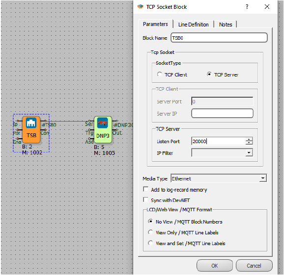
To enable the IEC104 protocol over RTU, you need to add an IEC104 Slave block to the Telediagram project and connect the TCP Socket block to the "Ser" input of the IEC104 Slave block. In the TCP Socket block settings, the TCP Socket Type should be selected as "Server" and the listening port should be defined. To activate the TCP Socket block, the "Ena" input of the TCP Socket block should be connected to the High Gate block.
If you want to serve multiple servers, you need to add an IEC104 Slave block for each server in the Telediagram project.
The IEC104 ASDU address can be configured either from the block settings of the IEC104 Slave block or from the "Asd" input of the IEC104 Slave block.
The values of the IEC104 objects that are selected for periodic transmission will be sent to the server when a rising edge signal is received at the "Trg" input of the IEC104 Slave block. If there is no data transmission through periodic or trigger-based methods, the trigger input can be left unconnected.
If you want to open multiple IEC104 Slaves on the device, you should make the configuration from the "object sets" section in the block settings of the IEC104 Slave block. This section is used in conjunction with the variable address table. When defining IEC104 objects in the variable address table, the "object set no" entered should correspond to the object sets value.
For example, if the "object sets" value in the block settings of the IEC104 Slave block is set to 1, the "object set no" in the variable address table should be 0. (2^0=1)
If the "object sets" value is set to 2, the "object set no" in the variable address table should be 1. (2^1=2)
And if the "object sets" value is set to 8, the "object set no" in the variable address table should be 3. (2^3=8)
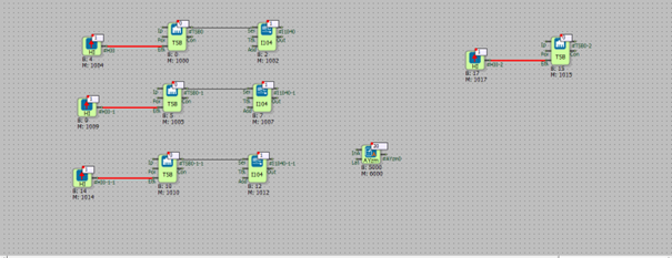
Sample Application
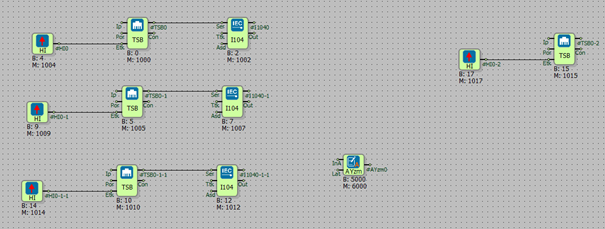
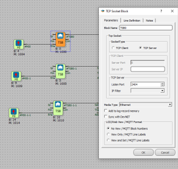
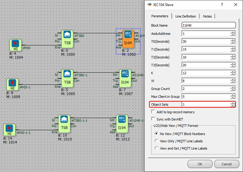
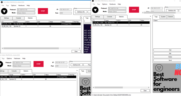
In the example application, three different IEC104 Slave blocks were defined for three different listening ports. During the configuration, each IEC104 Slave block was assigned a different "Object Sets" value.
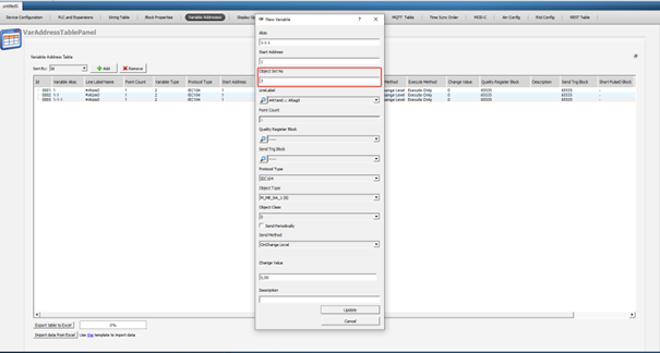
For listening port 2404, the "Object Sets" value of the IEC104 Slave block is specified as 1 in the block settings. Therefore, the corresponding "Object Set No" value in the variable address table is entered as 0. (2^0=1)
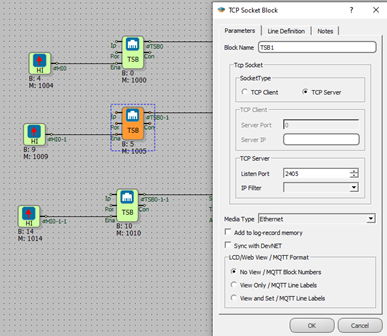
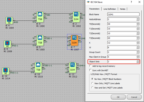
For listening port 2405, the "Object Sets" value of the IEC104 Slave block is specified as 2 in the block settings. Therefore, the corresponding "Object Set No" value in the variable address table is entered as 1. (2^1=2)
For listening port 2406, the "Object Sets" value of the IEC104 Slave block is specified as 8 in the block settings. Therefore, the corresponding "Object Set No" value in the variable address table is entered as 3. (2^3=8)
IEC 104 objects have been defined in the variable address table. A TCP connection has been established to the device, and online monitoring has been initiated.
IEC104 Masters were opened for different listening ports through the Vinci application, and the transmitted values were monitored.
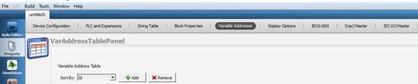
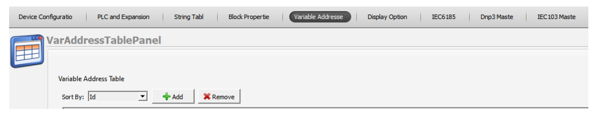
IEC104 Variable Address Table Definitions
Variable Address Table
With the addition of the IEC104 Slave Block to the Telediagram project, the IEC104 protocol becomes active within the RTU.
The association of variables with IEC104 is provided through the variable address table in the Telediagram project.
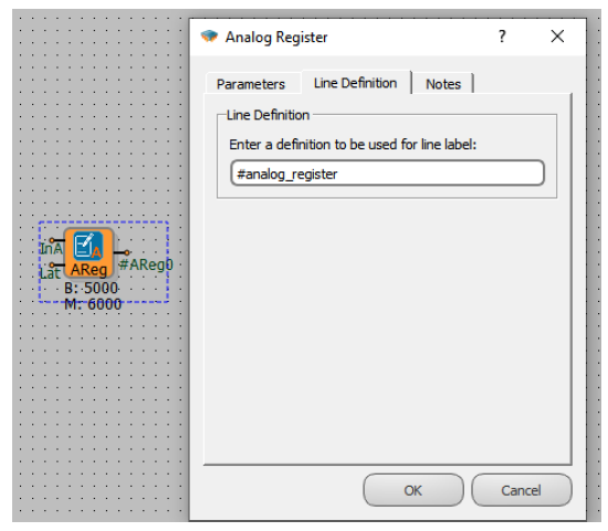
Defining Line Labels
In the Telediagram software, automatic line label is provided for all blocks added to the Telediagram project. To facilitate project readability, line label can be done based on the usage locations of the blocks.
Note: When defining line label, ensure not to leave any spaces and avoid using Turkish characters.
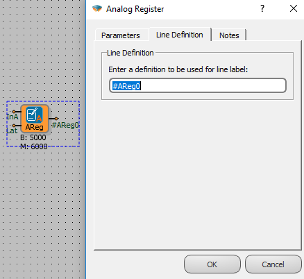
Attaching a Line Label
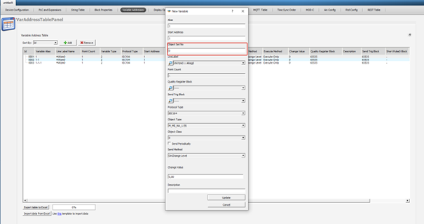
Associating protocol tags with line labels, variable address is provided from the menu by pressing "Add" button in the address table.
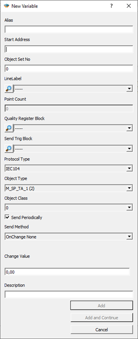
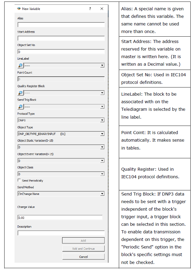
Alias: A special name is given that defines this defined variable.
Start Address: The address allocated for this variable on SCADA is written here. It is written as a decimal value.
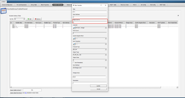
Object Set No: It is used to define multiple IEC104 Slaves. Through this value, IEC104 objects can be assigned to different Slave addresses. It is used in conjunction with the "Object Sets" section in the block settings of the IEC104 Slave block. For detailed information, please refer to the "Block Descriptions" section.
Line Label: The block to be associated on the Telediagram is selected with the line label.
Point Count: Calculated automatically. It makes sense on tables.
Quality Register Block: Block entry to define Quality Register. For detailed information, please refer to the "Quality Register Block Settings" section.
Send Trig Block: If you want to send IEC104 data with an independent trigger from the trigger input of the block, the trigger block is selected from this section and the periodic send option in the block special settings must not be ticked in order to send trigger-dependent data here.
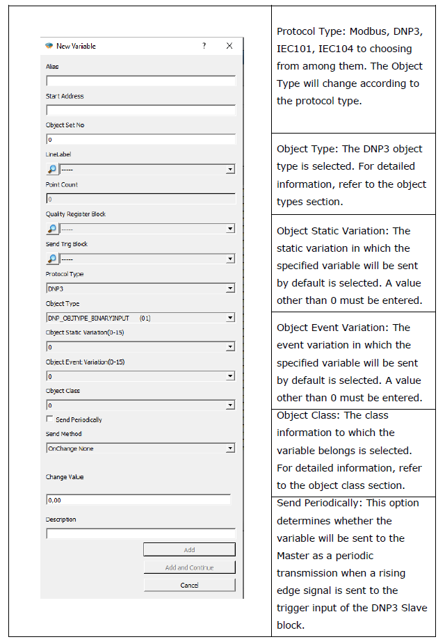
Protocol Type: Modbus, Dnp3, IEC101, IEC104 are selected. Object type will change according to protocol type.
Object Type: IEC104 object type information selected. For detailed information, please refer to the "Object Types" section.
Object Class: The class information to which the variable belongs is selected.
Send Periodically: It is the selection of whether to send periodic sending to SCADA in this variable when the trigger is detected from the Trigger input on the IEC104 Slave block.
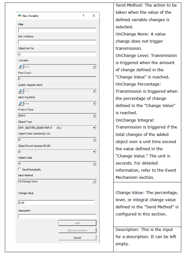
Send Method: If the value of the defined variable is changed, the operation to be performed is selected.
On Change None: The spin submission is not triggered.
On Change Level: When the amount defined in "Change Value" changes, sending is triggered.
On Change Percentage: Sending is triggered when there is a change in the percentage defined in "Change Value".
On Change Integral: If the accumulated change of the added object within the unit time, defined by the "Change Value," exceeds, the transmission is triggered. The unit is in seconds. For detailed information, please refer to the "IEC104 Event Mechanism" section.
Change Value: Sets the percentage or level change value together with the "Send method".
Description: It is the description input.
IEC104 Object Types
IEC104 Read Direction Object Types
| IEC104 Object | Pe |
|---|---|
| 1 (single-point) | Binary, Word, Analog, Long |
| 3 (double-point) | Word, Analog, Long |
| 5 (step position) | - |
| 7 (bitstring) | - |
| 9 (measured normalized value) | Binary, Word, Analog, Long |
| 11 (measured scaled value) | - |
| 13 (measured short floating point) | Binary, Word, Analog, Long |
| 15 (integrated totals) | - |
| 20 (packed single-point) | - |
| 21 (normalized value without quality descriptor) | - |
| 30 (single-point information with time tag) | Binary, Word, Analog, Long |
| 31 (double-point information with time tag) | Word, Analog, Long |
| 32 (step position information with time tag) | - |
| 33 (bitstring of 32 bit with time tag) | - |
| 34 (measured normalized value with time tag) | Binary, Word, Analog, Long |
| 35 (measured scaled value with time tag) | - |
| 36 (measured short floating point number with time tag) | Binary, Word, Analog, Long |
| 37 (integrated totals with time tag) | - |
| 38 (event of protection equipment with time tag) | - |
IEC104 Object Types in Control Direction
The write variable is also automatically created for each block matched with the read type. Variable types that can be accessed as writing to defined read objects are as follows:
| Selected for a reading - IEC104 Object Types | IEC104 Object Types - That can be accessed for writing to the same data point |
|---|---|
| 1 (single-point) | 45 (single command), 58 (single command with time tag) |
| 3 (double-point) | 46 (double command), 59 (double command with time tag) |
| 13 (measured short floating point) | 50 (set point command, short floating point), 63 (set point command, short floating - point number with time tag |
| 30 (single-point information with time tag) | 45 (single command), 58 (single command with time tag) |
| 31 (double-point information with time tag) | 46 (double command), 59 (double command with time tag) |
| 36 (measured short floating point number with time tag) | 50 (set point command, short floating point), 63 (set point command, short floating - point number with time tag) |
Quality Register Block Settings
Quality Descriptor (QDS) bits and accordingly Quality Register Block Settings are supported in our devices. Quality Descriptor bit definitions; OV, BL, SB, NT, IV, CY, CA, EI. As it is known, the use of QDS varies according to the defined object types. The Quality Descriptor (QDS) identification table is shown below.
| Status / QDS | OV | CY | CA | EI | BL | SB | NT | IV |
|---|---|---|---|---|---|---|---|---|
| overflow quality flag | carry flag | adjusted flag | blocked quality flag | substituted quality flag | topical quality flag | invalid quality flag | ||
| 1 | overflow | carry | counter was adjusted | elapsed time not valid | blocked | substituted | not topical | invalid |
| 0 | no overflow | bo carry | counter was not adjusted | elapsed time valid | not blocked | not substituted | topical | valid |
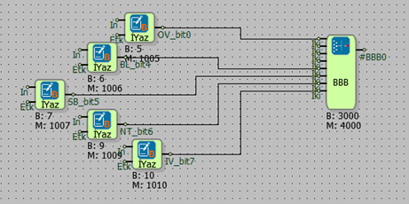
The QDS values to be used are created with the Bit Combination Block and defined by the Quality Register Block setting during the IEC 104 association in the variable addresses section.
For example, we will define the reading value with the IEC 104 protocol. We select 36 – measured short floating point number with time tag, as the reading object type. We will define QDS values for Quality Register Block definition. For this, the QDS bit definition is as follows; It should contain 0.bit OV, 4.bit BL, 5.bit SB, 6.bit NT, 7.bit IV. We can define Bit Combining Block as Quality Register Block.
Command Send Settings
It supports Single Command, Double Command and Set Point Command for appropriate object types in IEC 104 protocol. Object types command types mapping is shown in the Object Types Table. The settings are as follows; Depending on the object type, the options appear automatically in the selected IEC 104 protocol settings during line label association.
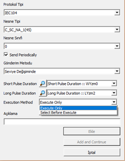
For example, when Object type 45 (Single Command) is selected, options for parameter settings become active as seen in Figure 2. A register is selected for either Short Pulse Duration or Long Pulse Duration values. It should be noted that the entered value will be treated as ms.
The Execution Method is also selected from the list. The Execution Method is of 2 types. Execute Only is selected if the operation is desired to be performed with a single command. If 2 different confirmation states are desired, Select Before Execute is selected.
For example, the Select Before Execute option can be used for transactions that require confirmation with 2 different commands. For this, the Select command must be sent first and then the Execute command.
IEC 104 Event Mechanism
The variable address table has a send on exchange selection for IEC 104 objects. The selection of the action to be taken when the value of the variable defined in the variable address table changes is determined by the send method defined in the variable address table. The send method is used in conjunction with the change value section.
On Change None: The spin submission is not triggered.
On Change Level: When the amount defined in "Change Value" changes, the sending is triggered.
On Change Percentage: Sending is triggered when there is a change in the percentage defined in "Change Value".
On Change Integral: If the accumulated change of the added object within the unit time, defined by the "Change Value," exceeds, the transmission is triggered.
The "Change Value" in conjunction with the "Send Method" sets the percentage, level, and integral change value.
For example, if the send method for the IEC104 object defined in the variable address table is set to "Integral Change" and the change value is set to 10:
When the change amount of the defined variable is 2 (the difference between the current value and the previous value of the defined variable), the transmission will be triggered after 5 seconds (10 divided by 2, based on the change value entered in the variable address table).
When the change amount of the defined variable is 5, the transmission will be triggered after 2 seconds (10 divided by 5).
When the change amount of the defined variable is 15, the transmission will be triggered immediately as it exceeds the change value entered in the variable address table.
The RTU device tags the statuses that are send on change and change detected as events and assigns a time tag to the event. In case of a tagged event, if there is a connection with the server, the relevant object is transmitted immediately as COT 0x03 Spontaneous.
If there is no connection with the server, the device is added to the event log memory and stored for sending when the server connection is established again. For storage, the option "Add to log-record memory" must be selected in the IEC104 Slave block settings.
Note: If all tags are to be sent to the server when the connection is established, the Sync with DevNET option must be selected in the IEC104 Slave block settings.
Note: The values of selected objects with periodic sending between IEC104 objects are not detected as events. That is, periodic submissions are not added to the log memory when there is no connection.
IEC104 Redundancy Group Specification
Note: The settings described below are valid for Telediagram version before 18.
For version 18 and later, the adjustments are made through the block settings of the IEC104 Slave Block in Mikroterminal.
Mikrodev RTU can connect with IEC 104 Master as IEC 104 Slave. The number of Master IPs to be connected to this must be defined to the device with the AT command and via the IEC104 Slave block.
For Telediagram version before 18:
The Mikroterminal application opens, from the special command entry section.
The command AT+OPTIONS=7,< NUMBER OF MASTER IP TO CONNECT > is sent.
For example, if Edaş has two different server IPs, this command would be as follows:
AT+OPTIONS=7,2
AT+OPTIONS=7,2 Write Commad OPTIONS=OK
AT+OPTIONS=7,? Read Command OPTIONS=2
After entering this parameter, the device must be reset. AT+RESET=1
Note: The maximum number of Masters that the IEC104 Slave block can connect to is 2 for RTU series devices and 4 for DM series devices.
For Telediagram version 18 and later, please refer to the "Block Settings" section for Redundancy Group definition.
Ability to Edit the Analog Threshold Value Retained in the Log Recording Memory
While there is no connection, changes can be made on the threshold values of the analog values kept in the log memory.
The Mikroterminal application opens, will be sent from the custom command line
AT+OPTION=8,< ANALOG EVENT MULTIPLIER >
Analog event multiplier on the command line, analog log recorded when there is no connection, it allows to operate on the threshold values of the values. Values written here are from 0 if set differently, when there is no connection, the event threshold is multiplied by the coefficient here.
For example;
If AT+OPTION=8.0, analog events are not added to the log memory if there is no connection.
If AT+OPTION=8.1, it records the change in the log memory as much as the value entered in the variable table.
If AT+OPTION=8.10, a change that is 10 times larger than the value entered in the variable table will also be recorded in the log memory.
AT+OPTIONS=8,10 Write Command
OPTIONS=OK
AT+OPTIONS=8,? Read Command
OPTIONS=10
After entering this parameter, the device must be reset. AT+RESET=1
Note: The threshold value entered here applies to all defined IEC104 Slaves in the project.
IEC104 Connection Information Learning Command
IEC104 connection information can be learned with AT command.
For Telediagram version before 18:
The Mikroterminal application opens, from the custom command input.
The command AT+COMSTATUS=iec104 is sent.
IEC104 redundancy group number =2 command query example when there is no selected connection;
AT+COMSTATUS=iec104
IEC104 CLIENT GROUP[0]:00000000
isDataTransStarted:0
NumofActiveConnections:0
MaxNumberOfEvents:256
RefInstance:200111b8
EventItems:1000c800
ObjMap:10005ab0
connection[0]:00000000
connection[1]:00000000
connection[2]:00000000
connection[3]:00000000
connection[4]:00000000
IEC104 CLIENT GROUP[1]:00000000
isDataTransStarted:0
NumofActiveConnections:0
MaxNumberOfEvents:256
RefInstance:200115f8
EventItems:1000dc00
ObjMap:100064f4
connection[0]:00000000
connection[1]:00000000
connection[2]:00000000
connection[3]:00000000
connection[4]:00000000
COMSTATUS=
IEC104 redundancy group number =2 selected, command query example when there is only one connection;
AT+COMSTATUS=iec104
IEC104 CLIENT GROUP[0]:4d0aa8c0
isDataTransStarted:1
NumofActiveConnections:1
MaxNumberOfEvents:256
RefInstance:2000f4c8
EventItems:1000c800
ObjMap:1000518c
connection[0]:20010b30
DataTransStarted: 1
connection[1]:00000000
connection[2]:00000000
connection[3]:00000000
connection[4]:00000000
IEC104 CLIENT GROUP[1]:00000000
isDataTransStarted:0
NumofActiveConnections:0
MaxNumberOfEvents:256
RefInstance:2000f908
EventItems:1000dc00
ObjMap:100052ac
connection[0]:00000000
connection[1]:00000000
connection[2]:00000000
connection[3]:00000000
connection[4]:00000000
COMSTATUS=
For Telediagram version 18 and later:
The Mikroterminal application opens, from the custom command input.
The command AT+COMSTATUS=iec104,< block number > is sent.
The block number specified on the command line is the block number of the IEC104 Slave block from which the connection information is to be retrieved.
IEC104 redundancy group number =2 command query example when there is no selected connection;
AT+COMSTATUS=iec104,2
IEC104 CLIENT GROUP[0]:d20aa8c0
isDataTransStarted:0
NumofActiveConnections:0
MaxNumberOfEvents:85
RefInstance:200100d0
EventItems:1000c800
ObjMap:10005134
connection[0]:00000000
connection[1]:00000000
connection[2]:00000000
connection[3]:00000000
connection[4]:00000000
IEC104 CLIENT GROUP[1]:390aa8c0
isDataTransStarted:0
NumofActiveConnections:0
MaxNumberOfEvents:85
RefInstance:20010518
EventItems:1000cea4
ObjMap:1000518c
connection[0]:00000000
connection[1]:00000000
connection[2]:00000000
connection[3]:00000000
connection[4]:00000000
COMSTATUS=
IEC104 redundancy group number =2 selected, command query example when there is only one connection;
AT+COMSTATUS=iec104,2
IEC104 CLIENT GROUP[0]:d20aa8c0
isDataTransStarted:1
NumofActiveConnections:1
MaxNumberOfEvents:85
RefInstance:200100d0
EventItems:1000c800
ObjMap:10005134
connection[0]:20012bc0
DataTransStarted: 1
connection[1]:00000000
connection[2]:00000000
connection[3]:00000000
connection[4]:00000000
IEC104 CLIENT GROUP[1]:390aa8c0
isDataTransStarted:0
NumofActiveConnections:0
MaxNumberOfEvents:85
RefInstance:20010518
EventItems:1000cea4
ObjMap:1000518c
connection[0]:00000000
connection[1]:00000000
connection[2]:00000000
connection[3]:00000000
connection[4]:00000000
COMSTATUS=
Command to Learn IEC104 Master IPs Connected to TCP Socket Block
With AT command, IEC104 Master IPs connected to TCP Socket block can be learned.
The Mikroterminal application is opened, from the special command entry or from the command line that says AT+STATUS= in the Socket Status section.
The AT+SOCKET=< TCP Socket Block Number > command is sent.
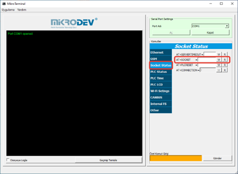
Example of IEC104 Master IP Query connected to TCP Socket block with 4 block numbers;
AT+SOCKET=4
Ip: 172.21.1.1, Port: 65063, Status: 2
Ip: 172.21.1.1, Port: 65514, Status: 3
Ip: 172.21.1.2, Port: 46076, Status: 2
Ip: 172.21.1.2, Port: 45799, Status: 2
AT+COMSTATUS=iec104
IEC104 CLIENT GROUP[0]:020115ac
isDataTransStarted:1
NumofActiveConnections:2
MaxNumberOfEvents:256
RefInstance:200110b0
EventItems:1000c800
ObjMap:10005ab0
connection[0]:20014b78
DataTransStarted: 1
connection[1]:00000000
connection[2]:20013430
DataTransStarted: 0
connection[3]:00000000
connection[4]:00000000
IEC104 CLIENT GROUP[1]:010115ac
isDataTransStarted:1
NumofActiveConnections:2
MaxNumberOfEvents:256
RefInstance:200114f0
EventItems:1000c900
ObjMap:100064f4
connection[0]:20013838
DataTransStarted: 0
connection[1]:00000000
connection[2]:20014770
DataTransStarted: 1
connection[3]:00000000
connection[4]:00000000
COMSTATUS=
DNP3 SLAVE Driver
General Information
DNP3 protocol is a distributed communication protocol. Primary advantage are:
• Time-labeled variable support
• Ability to re-send the events that occurred during the absence of communication when connected with the time tags.
• The ability of SCADA to automatically send changes without the need to query.
• Ability to query multiple variables as a class, not individually
• Time syncronization
DNP3 Slave Driver
Mikrodev RTU devices are supports DNP3 SLAVE mode and gives service to DNP3 supported systems over TCP IP and/or Serial Port . The following services are supported:
1- Bulk object reading with Class object query
2- Adding Object Static Variation and Object Event Variation (based on the object types of the specified variables)
3- Time syncronization
4- Event control in instantaneous measurement data as a percentage and level
5- Automatic send the event datas
6- Periodically send the points of data
DNP3 Slave Block Definitions
Connections
Connections Explanation
Ser: TCP Socket Input
The TCP server socket block, where the DNP3 protocol will run, is connected from this input.
Trg: Trigger Input
The trigger input for periodically send operation. Works as a rising edge.
Asd: Asdu Address Input
It is used as an ASDU address entry.
#DNP30: Connection Status
It is used to control the connection status between the master and the slave. DNP3 gives the value 1 when the connection with the master is established.
Block Special Settings
Adding a DNP3 Slave block to the project activates the DNP3 protocol on the RTU.
Serial Input: A TCP or Serial Port block is added to the serial input of the DNP3 block.
Note: To serve multiple servers, a DNP3 Slave block must be added to the telecontrol project for each server.
Trg Input: On the rising edge of the trigger, selected objects with active periodic transmission among the DNP3 objects are sent to the server with a Periodic Cause of Transmission (COT). This input can be left empty if periodic transmission is not required.
Asd Input: If the DNP3 ASDU address needs to be configured externally instead of through block-specific settings, the Asd input is used.
#DNP30 Output: It is used to control the connection status between the master and the slave. DNP3 gives the value 1 when the connection with the master is established.
When a DNP3 Slave block is added to the RTU logic project, the DNP3 protocol becomes active on the RTU. The association of this protocol with the variables in the RTU is achieved through the variable address table. Variables defined in this table ensure proper communication with the master device.
Object 60 and Object 80 are critical elements of the DNP3 protocol and must be defined in the variable address table to enable communication with the master device:
• Object 60: Enables the classification and retrieval of event and static data. This object allows the master device to send queries targeting specific classes (Class 0, Class 1, Class 2, Class 3) and retrieve only the relevant data.
• Object 80: Serves to monitor the internal status and diagnostic information of the device. This object ensures control of diagnostic details such as the RTU’s health status and communication state.
To define Object 60 and Object 80 variables, navigate to the variable address table. Inputs such as tag names and starting addresses can be chosen arbitrarily.
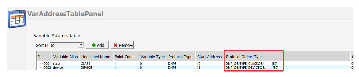
Note: If the DeviceObj (Object 60) and ClassObj (Object 80) variables are not defined in the variable address table, communication between the DNP3 Master and Slave cannot be established.
DNP3 Variable Table Definitions
Variable Table
To RTU logic project, DNP3 becomes active in the DNP3 protocol within the RTU with the addition of the Slave Block to DNP3. Variables that in the RTU logic, The association of DNP3 is provided in the variable address table.
Line Label Definition
A line tag can be defined for all blocks added to the telecontrol project. To associate protocol addresses in the variable address table, the relevant blocks must have a defined line tag.
Line Label Attribution
Associating the protocol adresses with line labelss, The variable is provided from the menu by pressing the “Add” button in the address table.
DNP3 Object Class
The class structure in the DNP3 protocol enhances communication efficiency by grouping data based on priority and categories. Data is organized into four main classes: Class 0, Class 1, Class 2, and Class 3. These classes are defined according to the object classes specified in the variable address table.
Class 0: This class is reserved for static (unchanging) data. Static data reflects the current value of a variable in a device. For example, information like the current measurement value of a sensor or the current position of a switch falls under Class 0. Class 0 data is typically low-priority and is sent only when requested by the master. Points assigned to Class 0 do not report events. Reading all static data types in a device is equivalent to reading Class 0.
Class 1: This class is used for high-priority event data. An event is triggered by a change in a data point or another trigger condition. Class 1 events are considered more urgent compared to other classes. Typically, high-priority information such as significant state changes or critical alarms is assigned to this class. For instance, an intrusion detection event in a security system could be reported as Class 1.
Class 2: This class is used for medium-priority event data. Class 2 events are less urgent than Class 1 events but have higher priority than Class 3 events. Moderately critical state changes or events are assigned to this class. For example, a warning signal from a device could be reported as Class 2.
Class 3: This class is used for low-priority event data. Class 3 events have the lowest priority among the classes. Routine events or less critical state changes are typically assigned to this class. For example, a device measurement exceeding a predefined range might be reported as Class 3.
Note: If you want to receive DNP3 data from the master device with the Unsolicited Enable query, the relevant address must have a class definition other than 0. Unsolicited messages cannot be sent to addresses with a class definition of 0. Therefore, the class structures of the variables must be carefully defined to ensure correct transmission of critical or event-based data.
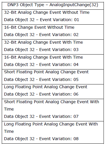
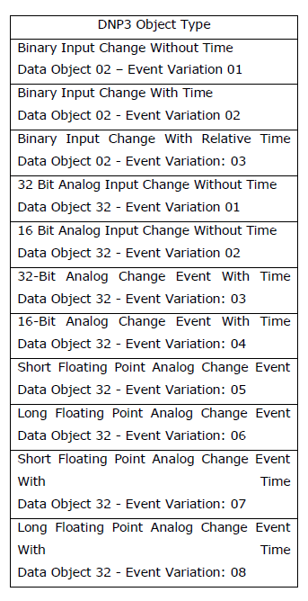
DNP3 Object Types
The DNP3 slave device responds to variation 0 commands for the object types listed below using the static and event variations defined in the variable address table. These objects are used to query and transmit change events or static states.
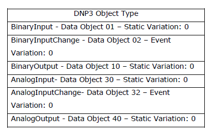
Note: The Binary Input Change and Analog Input Change object types are not defined in the variable address table. Instead, the Binary Input and Analog Input object types are used for change tracking. If the "send on change" feature is enabled for these objects, when a change occurs in these variables, the DNP3 Slave device responds to the Master device's query accordingly (Binary Input Change or Analog Input Change).
DNP3 Object Types in Reading Direction
According to the DNP3 protocol, when the master sends a Variation 0 query to the slave device, the slave device responds only with the static variations defined in the variable address table. In addition, when the master sends a query for a variable, for example, with variation 1, the slave device responds with variation 1, regardless of whether the relevant variable is defined with a different variation.
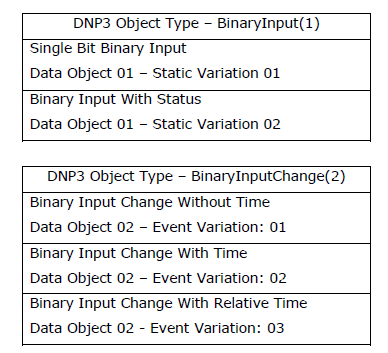
Supported Variations of Binary Input Variables
Supported Variations of Binary Output Variables

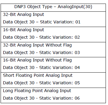
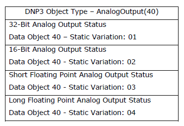
Supported Variations of Analog Input Variables
Supported Variations of Analog Output Variables
Note: No variations other than those supported by the variables should be defined. The slave device only supports the variations specified here. Therefore, using different variations may lead to communication errors.
Note: Variation 0 is used by the master device to query the variations defined by default on the slave device. Therefore, variation 0 should not be defined on the slave device.
DNP3 Object Types in Control Direction
The object types supported in the control direction on the slave device are as follows:

There are 2 different control object types defined in the variable address table in the device. These are Control Relay (12) and Control Analog (41) object types.
DNP3 Event Mechanism
Event Definition for DNP3 Objects
The Binary Input Change and Analog Input Change object types are not defined in the variable address table. Instead, Binary Input and Analog Input object types are used for change tracking. If the "send on change" feature is enabled for these objects, the DNP3 Slave device responds to the Master device's query appropriately when a change occurs in these variables. This process occurs only when the change is recorded as an event within the corresponding data class, ensuring that only current or updated data is prioritized in communication.
In the variable address table, the "send on change" option is available for DNP3 objects. The action to be performed when the value of the defined variable changes is selected through this menu: OnChange None: Value changes do not trigger a transmission.
OnChange Level: Transmission is triggered when the change reaches the amount defined in the "Change Value."
OnChange Percentage: Transmission is triggered when the change reaches the percentage defined in the "Change Value."
OnChange Integral: Transmission is triggered when the total of the changes within a unit time exceeds the value defined in the "Change Value."
The Change Value setting, together with the Send Method, configures the percentage, level, or integral change value.
Example; If the transmission method for a DNP3 object defined in the variable address table is set to "integral change" and the change amount is set to 10, the following behavior occurs:
If the change amount is 2, the transmission will occur after 5 seconds, calculated as 10/2(change value divided by the change amount).
If the change amount is 5, the transmission will occur after 2 seconds, calculated as 10/5. If the change amount is 15, the transmission will trigger immediately since it exceeds the defined change value.
This mechanism ensures efficient communication by sending only the necessary data based on the configured conditions.
Instant Transmission of DNP3 Event Statuses
The DNP3 Slave device labels the conditions defined as "Send on Change" and the changes detected as events. When a tagged event occurs:
If the connection between the slave and the master exists and the master is enabled to accept unsolicited messages, the corresponding object is immediately transmitted as an unsolicited message.
Note: Unsolicited sending is only performed if the master supports this feature and is set to active.
Note: If you want to receive DNP3 data from the master device with the Unsolicited Enable query, the relevant address must have a class definition other than 0. Unsolicited messages cannot be sent for addresses with a class definition of 0.
Event Statuses When There is No Connection with DNP3 Master
The RTU device labels the situations defined as send in change and the situations where change is detected as events. This data is stored in the device as Class data. This class event data stored in the memory can be read by the Master device with Class 1, Class 2 or Class 3 data read queries. If unsolisted sending is enabled, the RTU device automatically transmits this data to the master. If there is no connection between the slave and the master, the RTU device adds the class data to the event record memory and stores it to be sent when the connection is reestablished.
Note: For the storage process, the Add to log-recording memory option must be selected from the special settings of the DNP3 Slave block.
Note: If you want to send all class data stored in the log-recording memory to the master when the connection is established, the Synchronize with DevNET option must be selected from the special settings of the DNP3 Slave block.
Note: The values of objects that are selected as active for periodic sending between DNP3 objects are not perceived as events. In other words, periodic sendings are not added to the log-recording memory when there is no connection.
Events in DNP3 variables are transmitted via the DNP3 object types specified in the table below:
Using Mqtt
General Information
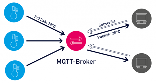
MQTT (Message Queuing Telemetry Transport) protocol is a machine-to-machine (M2M) message-based protocol widely used on the Internet. It has been adopted in the Internet of Things (IoT) ecosystem with its light weight and low resource consumption. Almost all IoT cloud platforms support MQTT protocol to send and receive data from smart objects.
Block Definitions
MQTT Config Block
To configure MQTT settings, you must first add the Mqtt Config block to your project.

Pin Definitions;
• Soc: It is used for TCP socket block connection. Mqtt Config block cannot be used without TCP socket block.
• Trg: When periodic data transfer is desired, a trigger should be given to the mqtt config block from this input. If this entry is left blank, data is transmitted according to other specified conditions.
• Mqtt0: Output showing the connection status. The information from this output is as follows;
      - 0: TCP Disconnected
      - 1: TCP Connecting
      - 2: MQTT Connecting
      - 3: MQTT Connected
• Sta: Output showing the communication status. The information from this output means:
      - 0: MQTT Send Conn Pack
      - 1: MQTT Idle Status
      - 2: MQTT Subscribe Status
      - 3: MQTT Publish Status
• Pub: Output showing Publish timeout.
Mqtt Config Block Custom Settings;
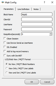
Definitions;
• Client Id: The field where the device is manually given an ID for the broker connection.
• User Name: The field where the device is named for the broker connection.
• Password: Password field entered in the device for the broker connection.
• Keep Alive: If the connection between the broker and the Publisher is lost, the waiting time before reconnecting.
• Clean Session: If selected, messages will be broadcast if there is communication between the device and the broker, otherwise the information recorded in communication interruptions will not be sent.
• Use Device Serial as User Name: If selected, the serial number of the device is used as the device username.
• SSL Enabled: It is marked to make the connection with SSL. (Only active in DM Series.)
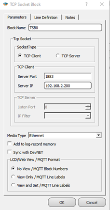
TCP Socket Block Connection
The output of the TCP Socket block is connected to the Soc input of the Mqtt Config block.

The special settings of the TCP Socket block should be made for mqtt connection as follows;
• TCP Client should be selected as the socket type,
• The mqtt server IP to be connected to the Server IP section must be entered,
• Mqtt server port information should be entered in the Server Port Section,
• As for the media type, Ethernet, GSM or WI-FI can be selected according to the characteristics of the microdev device used.
MQTT Table
The table where all MQTT-related adjustments are made can be accessed from the Projects/MQTT Table tab.
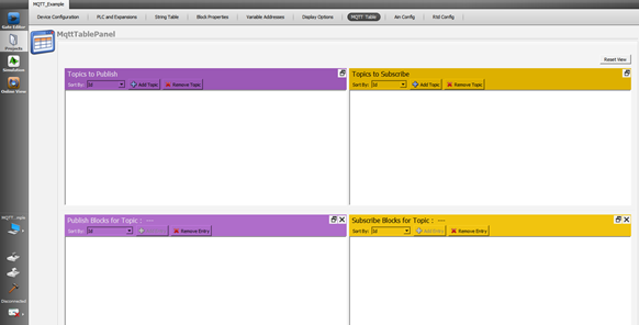
Topics The Publish
In this table, the Publish topic is entered to publish the data to the broker. The topic name is entered on the screen that appears by pressing the Add Topic button in the table. Block definitions where you can enable/disable Qos, Retain, Last Will, Payload settings, send on exchange and periodically send options are also made on this page.
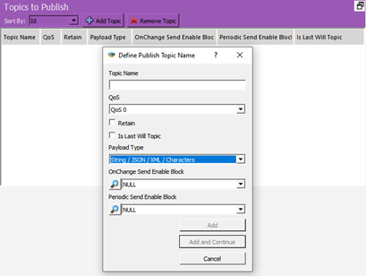
Definitions;
• Topic Name: The field where the topics you will send the messages are determined.
• QoS: Quality of Service refers to the agreement between the sender of a message and the receiver of the message. The QoS levels are as follows;
o QoS 0: Minimum data transfer is ensured. At this level, each message is forwarded to a subscriber and no confirmation is received that the message has arrived.
o QoS 1: The broker tries to transmit the message and waits for an acknowledgment response from the subscriber, if no confirmation is received within a specified time frame, the message is sent again.
o QoS 2: The broker receives two acknowledgments to ensure that the subscriber receives the message and only once.
• Retain: If this option is checked, if the connection between the broker and the subscriber is broken, the last value will be saved in memory.
• Is Last Will Topic: Last will topic. If a topic is created and this option is checked, the message under this topic will be forwarded to the subscribers when the device is disconnected from the broker.
• Payload Type: It is determined in which format the message content will be sent. Subscriber interprets incoming messages with this information. “MJson v1” can be selected if a time stamp is desired to be added to the sent messages.
• On Change Send Enable Block: Block selection added in the diagram to enable or disable the sending feature of the created topic on change.
• Periodic Send Enable Block: Block selection added in the diagram to enable or disable the periodic sending feature of the created topic.
Publish Blocks for Topic
In this table, the blocks to be published for the relevant Topic are selected. After clicking the topic in the Publish to topic table, the Add Entry button becomes active and by pressing this button, the block to be published in the project is selected. How to transmit the data can also be selected from the screen.
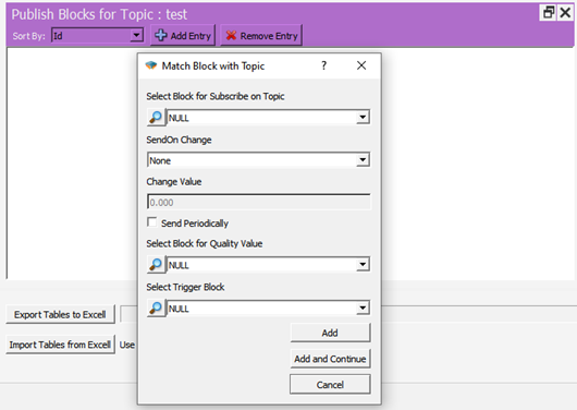
Definitions;
• Select Block for Subscribe on Topic: The area where the block that you want to send as a message in your project is selected.
• Send On Change: Send selection field on exchange
o On Level Change: Send when there is a change in the value specified in Change Value, if 0 is written, it will be sent in every change.

o On Percent Change: Send when there is a percentage change of value specified in Change Value, for example 10%.
• Change Value: Change amount input field.
• Send Periodcally: If checked, a message is sent every time a trigger comes to the trg input of the mqtt config block.
• Select Block for Quality Value: The block in which the Quality value included in the message content is selected in MJson v1 payload type.
• Select Trigger Block: Apart from change or periodicity, we can send the message by triggering the block we will specify here.
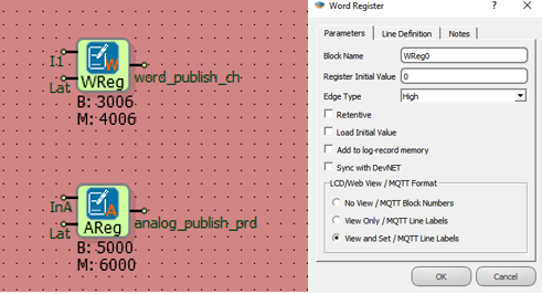
Note: Blocks used in messages; It can be sent and received with the block number (B:3006) under the block, or it can be added to the messages with line tags (word_publish_ch). This selection is made under the Mqtt Format tab in the block properties.
• Message that will appear if View and Set is selected;
![]()
• The message that will appear if No View is selected;
![]()
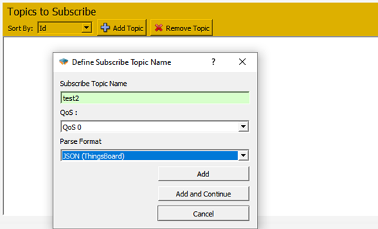
Subscribe to Topic
In this table, the relevant subscribe topic is entered to send data from the broker to the device.
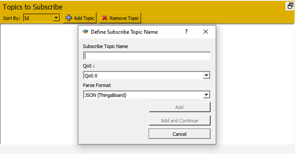
Definitions;
• Subscribe Topic Name: Enter the name of the topic to be subscribed to.
• QoS: Service quality level is selected.
• Parse Format: Select the format in which the messages will be parsed.
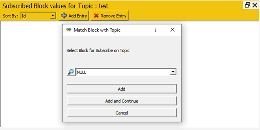
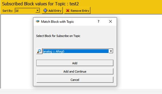
Subscribed Block Values for Topic
From this screen, the blocks to be associated for the subscribe topic are added. To use line tags, mqtt format should be selected as view and set from the special settings of the relevant block.
Special Applications
Ubidots
When you want to use Mikrodev PLC with ubidots mqtt, the following steps should be followed in addition to the settings described above;
From the Mqtt Config block custom settings, Ubidots ID should be entered in the Client Id section and the Token Key of the device created in Ubidots should be entered in the Username section.
Publish Topic: Enter as /v1.6/devices/< Device Name >. There is no need to define variables in the ubidots calculation for the blocks to be associated. With the first sent data, the variables are created automatically by Ubidots. The data is read on the Ubidots server with the block number or line tag.
Subscribe Topic: Entered as /v1.6/devices/< Device Name >/< Value Name >. A separate connection must be defined for each data to be subscribed. Data must be defined in the Ubidots environment. If the line tag is to be used, the variable created in Ubidots should have the same name as the line tag, if the line tag is to be transmitted only with the block number, the variable with the same name as the block number should be defined in the ubidots environment.
Example Applications
Topic Publish
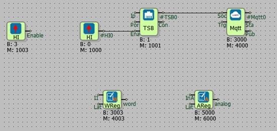
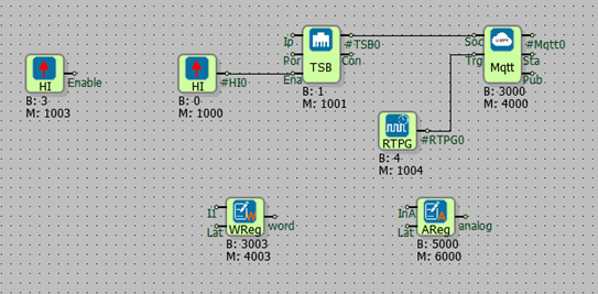
General Configuration; After the project is created, the diagram is designed as in the figure, the mqtt formats of word and analog registers are selected as view and set.
Send On Change;
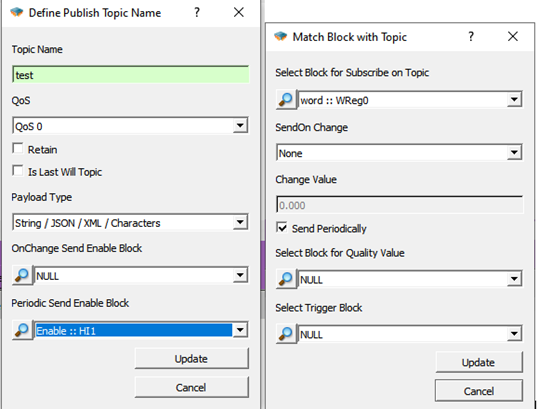
Follow Projects > MQTT Table >Topics to Publish > Add Topic.
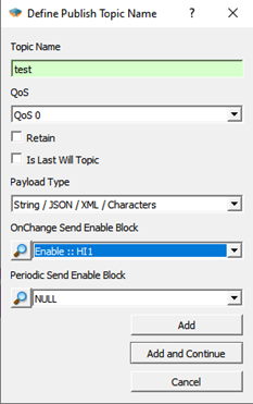
Select the Topic name, enter the High gate we have prepared in the diagram for the OnChange Send Enable Block, and click add.
Then, from the Publish Blocks for Topic section in a subtable, click to the Add Entry.
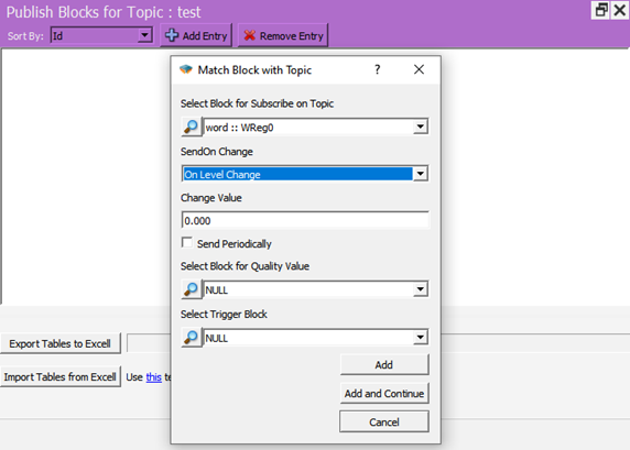
Select the block in the diagram that you want to broadcast as a message to the Select Block for Subscribe on Topic section. In the SendOn Change section, On Level Change is selected and Change Value is set to 0 so that it can send a message every time the value changes. Click on Add and continue.
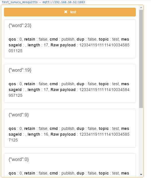
The project is loaded on the device and online monitoring is opened.
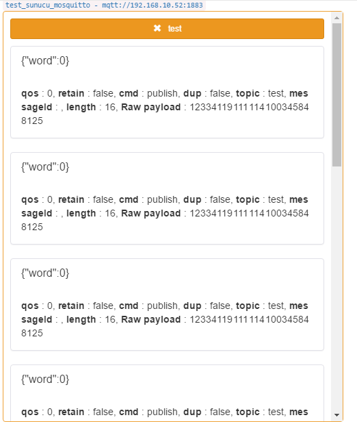
Subscribe to the topic opened with a program such as MQTTBox. After watching the mqtt config block value of 3 in online monitoring in the Mikrodiagram, when the value of the register is changed, it is seen that the value is published.
Periodic Send; In addition to the configuration sent in the change, a real time pulse generator is added to the trg input of the mqtt config block,
Real time pulse generator is set for 5 seconds to broadcast a message periodically every 5 seconds and the created topic is changed as follows. OnChange Enable Block= NULL and Set the High gate in the Periodic Send Enable Block diagram, In the Select Block for Subscribe on Topic section, select SendOn Change= None and click Send Periodically.
The project is loaded back to the device and incoming messages are observed.
Subscribe Topic
General Configuration;
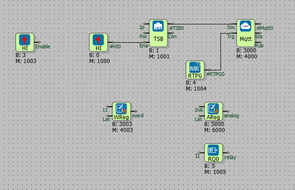
After the project is created, the diagram is designed as in the figure, the mqtt formats of the word and analog registers and the relay output are selected as view and set.
Follow Projects > MQTT Table >Topics to Subscribe > Add Topic.
Enter the topic name and click Add. Then, the add entry is clicked from the Publish Blocks for Topic section in a subtable.
Here, the block to which the subscribed value will be transferred is selected.

After all blocks to be subscribed are determined, the project is loaded into the device.
![]()
When the message is published to the test2 topic with the above format, the final state of the variables is as follows;

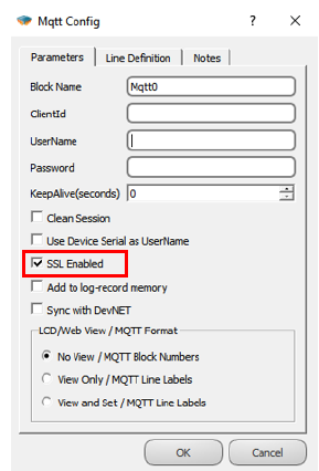
SETTING UP MQTT CONNECTION WITH SSL
Secure Sockets Layer (SSL) and Transport Layer security (TLS) are protocols that provide secure communications over a computer network or link. SSL/TLS provides data encryption, data integrity and authentication.
“SSL Enabled” option in block special settings of Mqtt Config Block; It provides secure MQTT connection with SSL Certificate. This option only active in DM Series.
In order to use this feature, an SSL Certificate must be uploaded on the device and the "SSL Enabled" option of the Mqtt Config block must be checked.
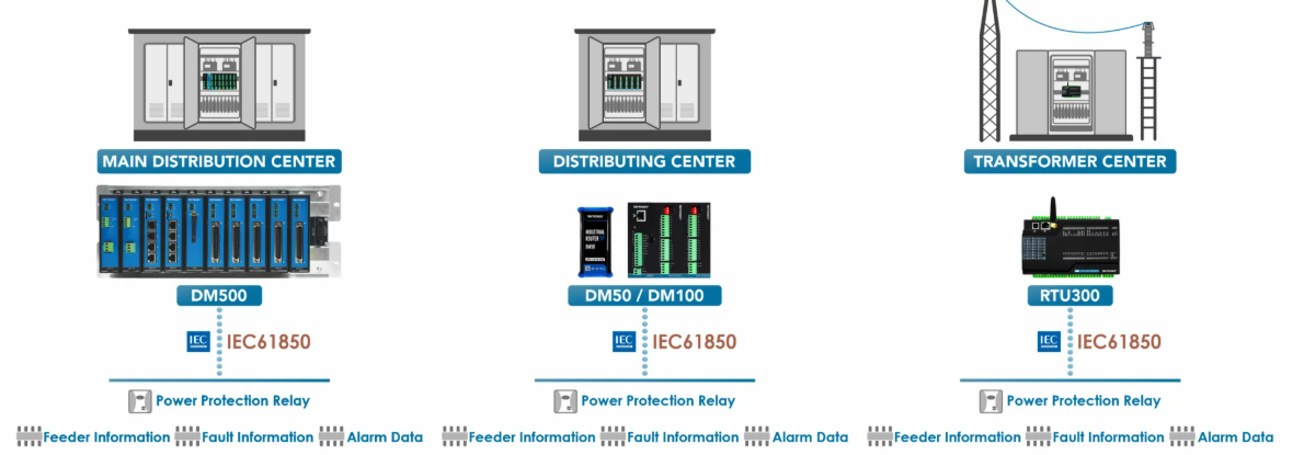
Using IEC61850
IEC 61850 is a communication protocol used especially in electrical distribution systems. It was developed to standardize and facilitate data exchange between components in the electrical power infrastructure. This standard ensures that components such as transformers, circuit breakers, protection relays, and other power grid elements can communicate securely and quickly with each other.
Mikrodev supports the IEC 61850 protocol in many of its RTU (Remote Terminal Unit) products. The necessary configuration can be easily done thanks to the IEC 61850 Browser tool in the Telediagram programming editor. The Mikrodev RTU device operates as a Client and uses files with the ".scl" extension to configure IEDs (Intelligent Electronic Devices).
There are three different data reading methods via the IEC 61850 Browser:
- Data Object Reading
- Dataset Reading
- Report Reading
These options determine which data will be retrieved and how, and ensure their association with the relevant blocks in the editor**. The settings made are exported and must be imported into the IEC 61850 Table Panel located in the Telediagram programming editor. Communication is completed by defining the IP address, port information, and connection commands of the IEDs via this panel.
Note: This document covers DM series Mikrodev devices with version 19 and above. For DM and RTU series devices with versions prior to 19, please refer to the IEC 61850 Application Note Version 1.0 document.
DATA OBJECT
Data Object Read
To create a new project using MDV61850 Browser, follow the steps below:
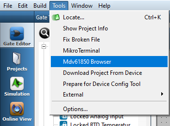
To open MDV61850 Browser, navigate to the Tools menu in the Telediagram program and click on the MDV61850 Browser option.
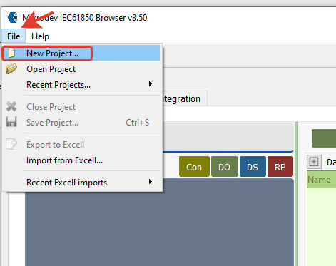
After opening MDV61850 Browser, click on the New Project option from the File menu.
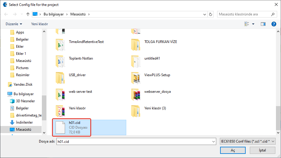
In the opened window, select the IEC 61850 configuration file (.cid, .icd, .scl) retrieved from the relay.
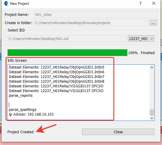
A project name is specified, and the file path where it will be saved is selected. A new project is created by clicking the Create Project button.
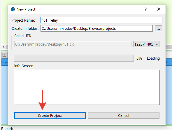
When a new project is successfully created, the Info screen displays information about the 61850 configuration file retrieved from the relay. If the message "Project created" appears on the screen, it means the process has been successfully completed.
Note: For detailed information about MDV61850 Browser, please refer to the MDV61850 Browser Application Note document.
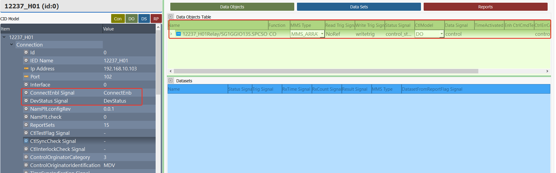
In MDV61850 Browser, the data objects to be read can be selected by double-clicking on them from the Data Objects List on the right. The selected data objects are then displayed in the Data Object Table.
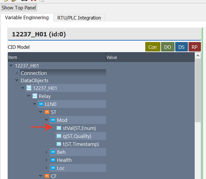
In the MMS_Type column, the variable type of the selected data is automatically updated. Based on the specified data type, a telediagram block should be assigned accordingly.
In the Connection section of MDV61850 Browser, the following telediagram blocks must be assigned to open/close the connection between the relay and RTU and to monitor the connection status:
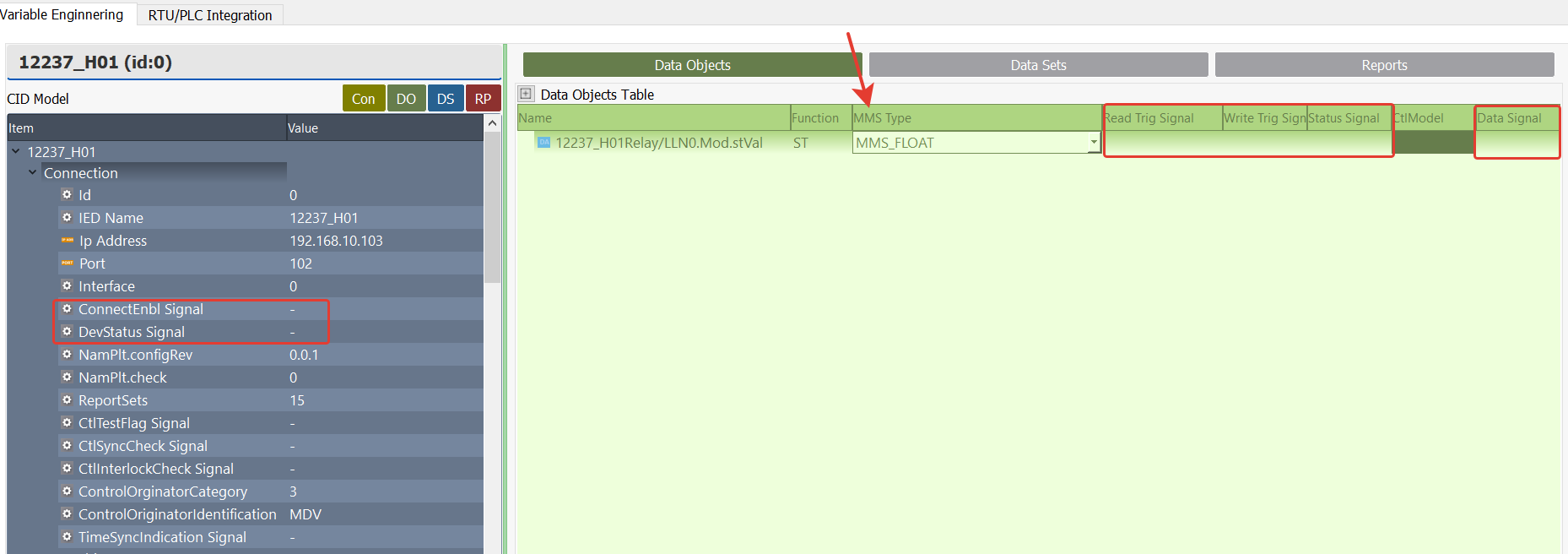
ConnectEnb Signal: This signal is used to control the connection between the relay and the RTU. A block to be associated from Telediagram is selected.
When a trigger signal (value 1) is applied to this label in Telediagram, the RTU connects to the relay and communication is initiated.
To disconnect, this signal must be set to 0.DevStatus Signal: This is a signal indicating the connection status and must be assigned with an appropriate block to be associated from Telediagram.
The possible values and their descriptions for this signal are as follows:
0 CLOSED Connection is closed.
1 CONNECTING Connecting.
2 CONNECTED Connected.
3 CLOSING Connection is being closed.
15 NAMEPLATE_SEND Nameplate information is being sent.
16 NAMEPLATE_WAIT Waiting for nameplate information.
17 NAMEPLATE_FAILED Nameplate information could not be retrieved (error occurred).
Note: When the CONNECTED (2) value is received, the connection between the RTU and the relay has been successfully established.
When CLOSED (0) or CLOSING (3) values are received, it indicates that the connection is closed or in the process of closing.
The values related to NAMEPLATE (15-17) are used during the connection process while retrieving device information from the relay.
Read Trig Signal: The trigger block to be associated in Telediagram to read the data object is selected.
Write Trig Signal: The trigger block to be associated in Telediagram to send a command to the data object is selected.
Status Signal: Used to track the status of read or write operations. The block to be associated from Telediagram is selected.
The possible values and their descriptions for this signal are as follows:
0: WAITING/FAIL, Request response is awaited or the operation failed
1: OK, The request was completed successfully.
2: MISMATCH, Operation failed due to incompatibility.
3: TIMEOUT, Operation failed due to timeout.
4: FAILED, Operation failed due to internal error.
100 and above: Operation failed due to library error. (Error code: can be calculated as status value + 100).
Note: When the Status Signal value is "1" (OK), the read or write operation has been completed successfully. When the value is "0" (WAITING/FAIL), the operation has failed or a response is being awaited.
Note: When the Status Signal is 100 or above, the value written in CtrlErrCode Signal should be checked for the error code.
The Library Errors and their descriptions written in CtrlErrCode are as follows.The value read should be the error code written here + 100. For example, the value to read for the IED_ERROR_NOT_CONNECTED code is 100+1 = 101.
* 0  IED_ERROR_OK: No error, service request completed successfully.
* 1  IED_ERROR_NOT_CONNECTED: Client is not connected, service request cannot be performed.
* 2  IED_ERROR_ALREADY_CONNECTED: Connection request failed because the client is already connected.
* 3  IED_ERROR_CONNECTION_LOST: Connection lost, service request cannot be performed.
* 4  IED_ERROR_SERVICE_NOT_SUPPORTED: Service or parameter not supported by client or server is being used.
* 5  IED_ERROR_CONNECTION_REJECTED: Server rejected the connection request.
* 6  IED_ERROR_OUTSTANDING_CALL_LIMIT_REACHED: Maximum concurrent call limit exceeded, new request cannot be sent.
* 10  IED_ERROR_USER_PROVIDED_INVALID_ARGUMENT: API function called with an invalid argument provided by the user.
* 11  IED_ERROR_ENABLE_REPORT_FAILED_DATASET_MISMATCH: Report activation failed, dataset mismatch.
* 12  IED_ERROR_OBJECT_REFERENCE_INVALID: Object reference is invalid.
* 13  IED_ERROR_UNEXPECTED_VALUE_RECEIVED: Unexpected type of object received.
* 20  IED_ERROR_TIMEOUT: Communication with the server failed, timeout occurred.
* 21  IED_ERROR_ACCESS_DENIED: Server denied access to the object or service.
* 22  IED_ERROR_OBJECT_DOES_NOT_EXIST: Server reported that the requested object does not exist.
* 23  IED_ERROR_OBJECT_EXISTS: Server reported that the requested object already exists.
* 24  IED_ERROR_OBJECT_ACCESS_UNSUPPORTED: Server does not support the requested access method.
* 25  IED_ERROR_TYPE_INCONSISTENT: Server reported that the requested object is not of the expected type.
* 26  IED_ERROR_TEMPORARILY_UNAVAILABLE: Object or service temporarily unavailable.
* 27  IED_ERROR_OBJECT_UNDEFINED: Requested object is not defined on the server.
* 28  IED_ERROR_INVALID_ADDRESS: Invalid address error.
* 29  IED_ERROR_HARDWARE_FAULT: Service failed due to hardware fault.
* 30  IED_ERROR_TYPE_UNSUPPORTED: Server does not support the requested data type.
* 31  IED_ERROR_OBJECT_ATTRIBUTE_INCONSISTENT: Server reported that the provided object attributes are inconsistent.
* 32  IED_ERROR_OBJECT_VALUE_INVALID: Server reported that the provided object value is invalid.
* 33  IED_ERROR_OBJECT_INVALIDATED: Object invalidated.
* 34  IED_ERROR_MALFORMED_MESSAGE: Message received from the server is in invalid format.
* 98  IED_ERROR_SERVICE_NOT_IMPLEMENTED: Service not implemented by the server.
* 99  IED_ERROR_UNKNOWN: Unknown error occurred.
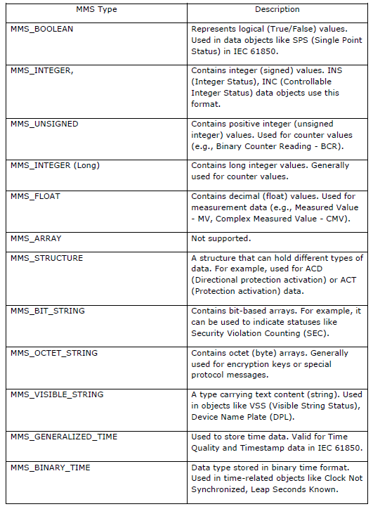
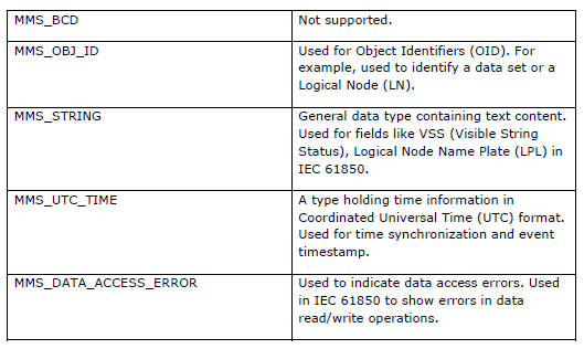
- MMS_Type: Variable type. This section is automatically updated according to the data object selected in the project. The variable type of the blocks to be associated in Telediagram is assigned according to the MMS type determined here.
Data Object Reading Application Example
The Telediagram application is opened, and a new project is created.
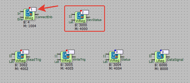
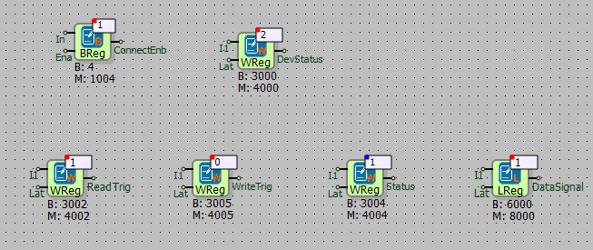
The signals defined in MDV61850 Browser are mapped to appropriate register types in Telediagram. In the example described here, the following registers are used:
- Status Signal: To monitor the read/write status of the data object.
- Data Signal: To retrieve the value of the data object.
- The Telediagram application is opened, and a new project is created.
- The signals defined in MDV61850 Browser are mapped to appropriate register types in Telediagram. In the example described here, the following registers are used:
ConnectEnb Signal → Binary Register
DevStatus Signal → Word Register
Read Trig Signal, Write Trig Signal, Status Signal → Word Register
Data Signal → Long Register (A block is added from Telediagram to the Data Signal section based on the variable type specified in the MMS Type column.)

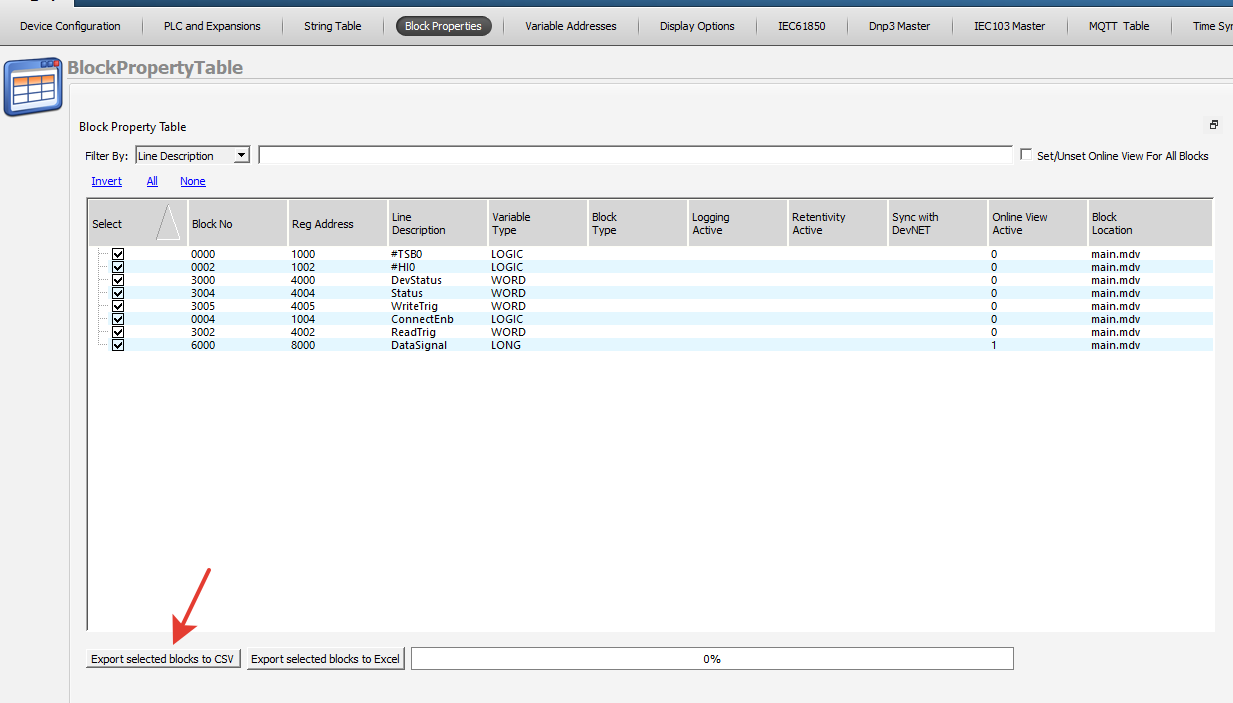
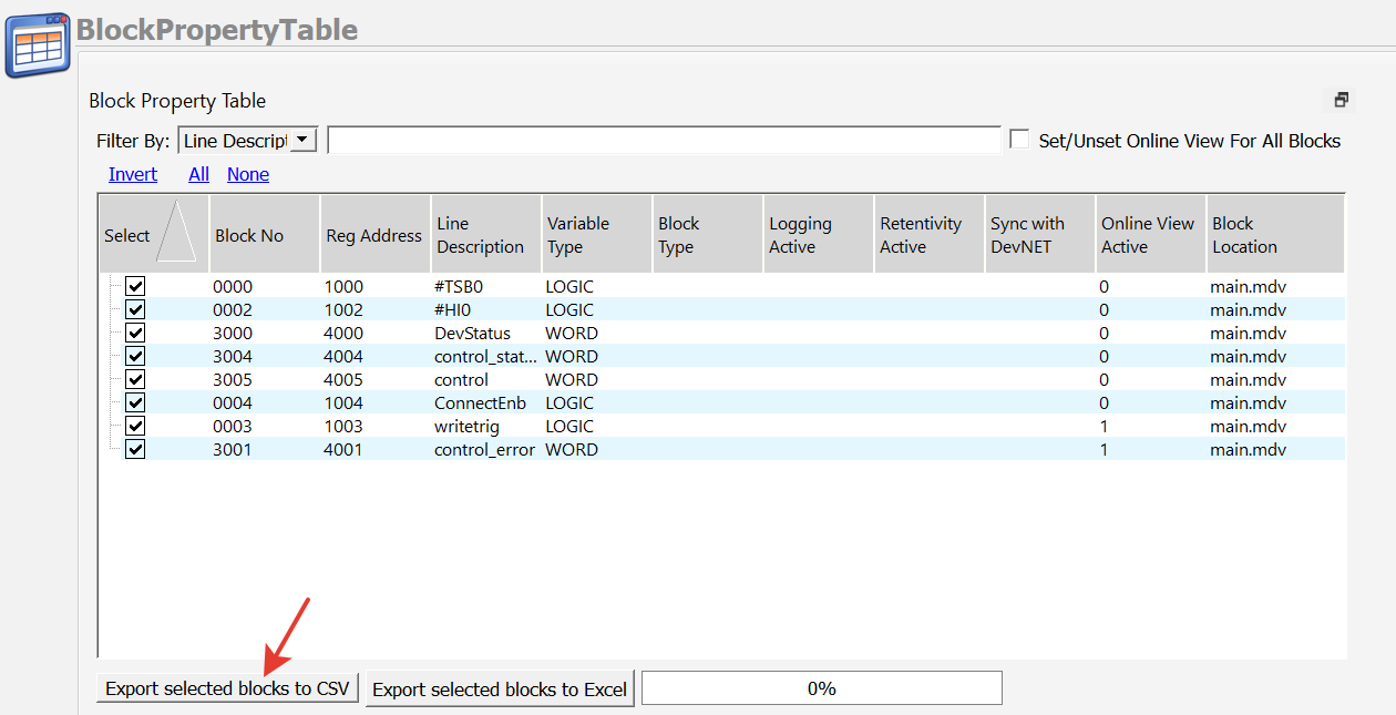
The blocks defined in Telediagram are exported in CSV format from the block properties table.
This process generates the data file required for integration with MDV61850 Browser.
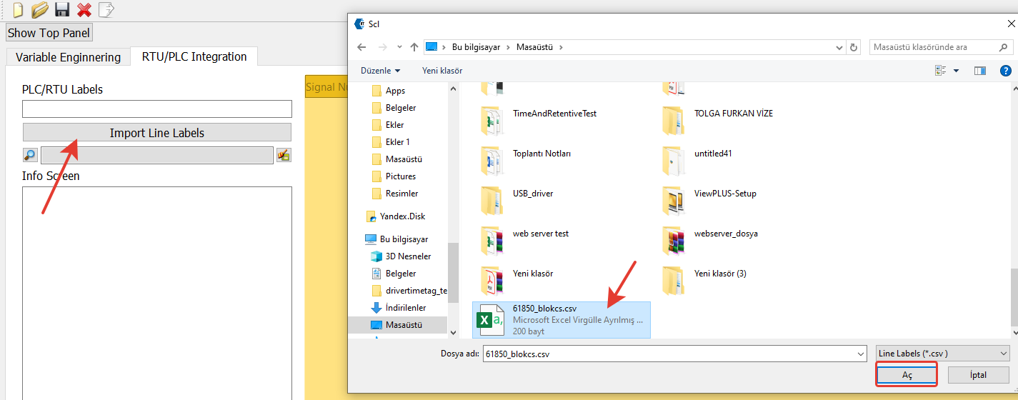
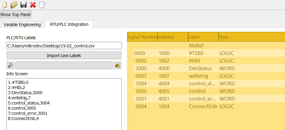
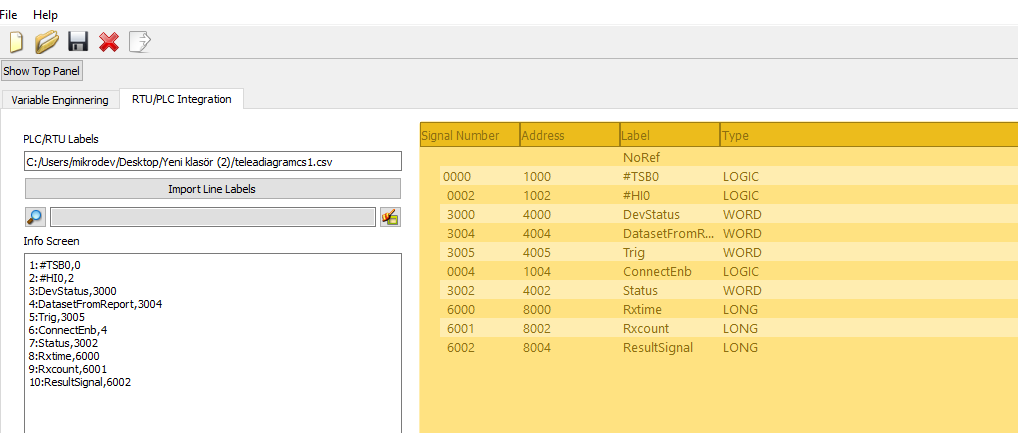
MDV61850 Browser is opened, and the RTU/PLC Integration section is accessed.
The CSV file obtained from Telediagram is imported.
Once the import is completed, the information screen displays the properties of the blocks.
On the right side of the screen, detailed information about the blocks is listed.

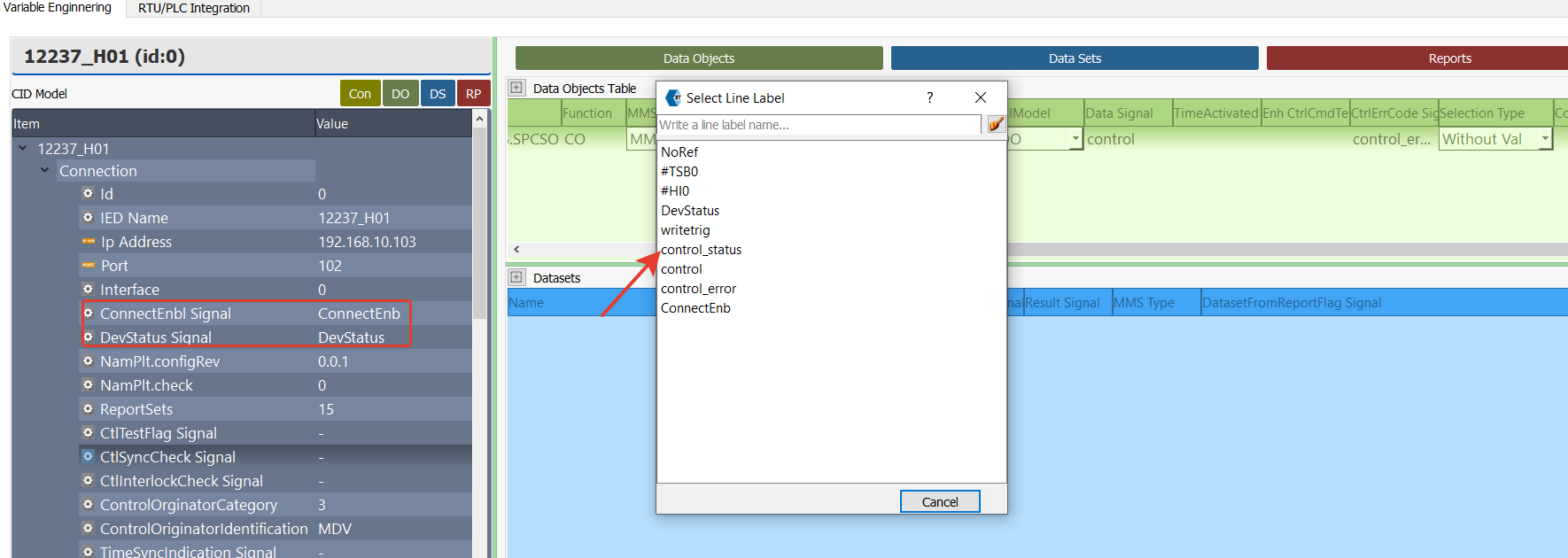
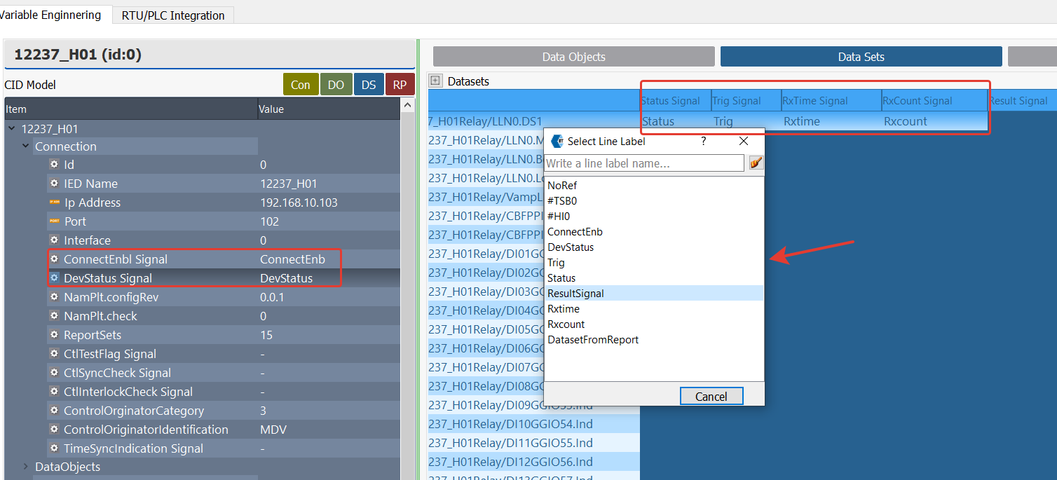
In MDV61850 Browser, the tag mapping process is performed using the following steps:
- Double-click on the relevant section where the tag should be mapped.
- In the Tag List window that appears, the available tags for mapping are displayed.
- Select the appropriate tag and map it to the corresponding section.

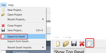
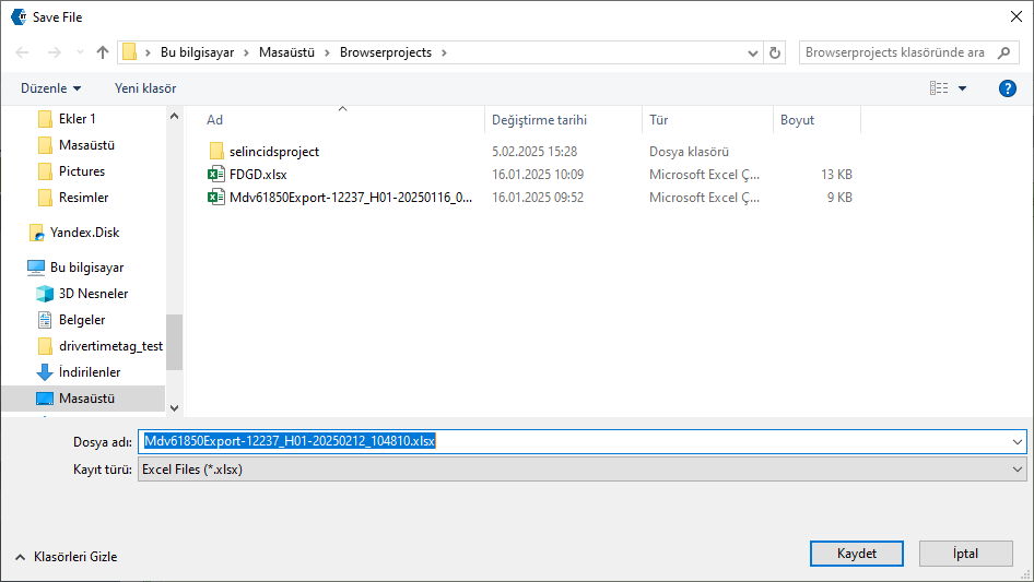
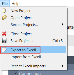
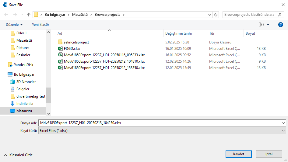
After completing the mapping process in MDV61850 Browser, the configuration can be exported in Excel format. From the File menu or file shortcuts, select the "Export to Excel" option.
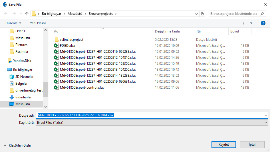
In the window that appears, select the file path where the Excel file will be saved and click the Save button.
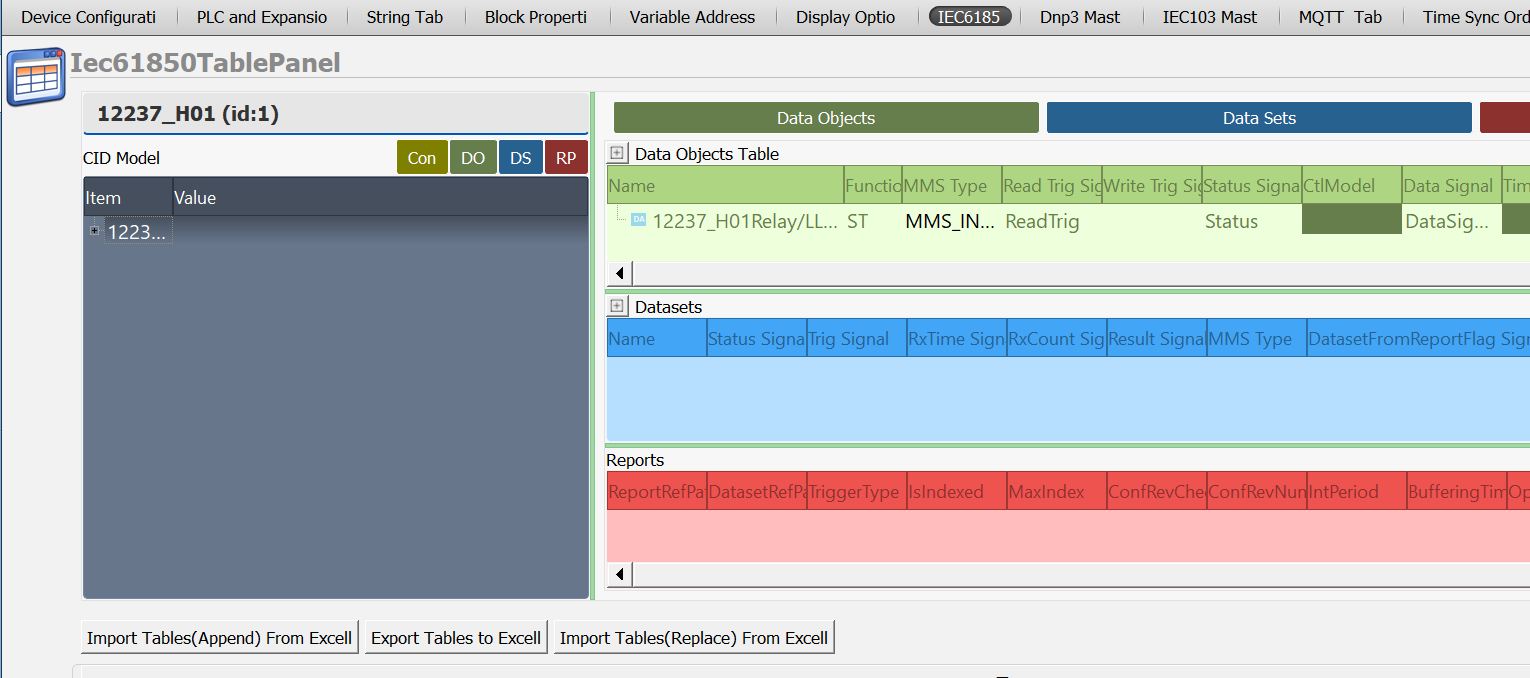
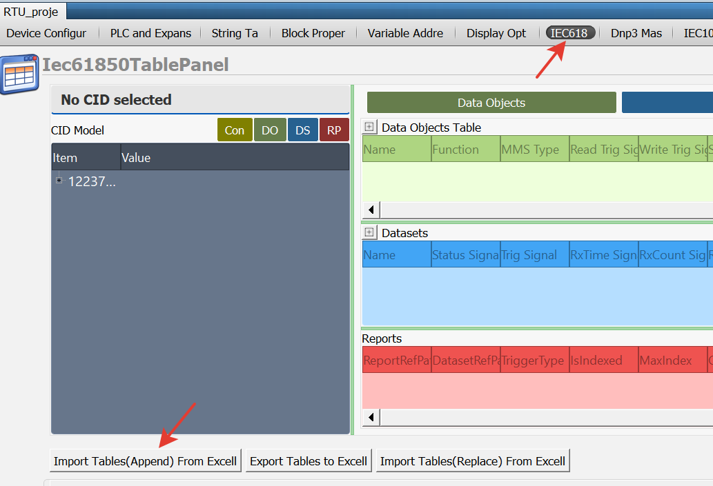
In Telediagram, the IEC 61850 table is opened, and the Excel file obtained from MDV61850 Browser is imported using the "Import tables (append) from Excel" option located at the bottom of the table.

Note: If a previously prepared IEC 61850 project exists and changes have been made in MDV61850 Browser, use the "Import Tables (Replace) from Excel" option to update only the relevant changes in the table.
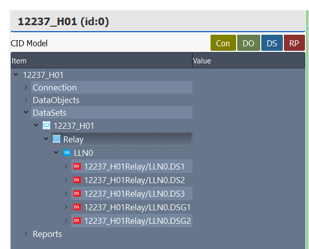
When the Excel file is imported, the IEC 61850 Table automatically populates with the blocks selected from the Browser.
Once these steps are completed, the configuration required for communication between the relay and the RTU is finalized.
Finally, the RTU project created in Telediagram is uploaded to the device, making the system ready for operation.
After completing the configuration in MDV61850 Browser and Telediagram, follow these steps to test whether communication between the RTU and the relay is successful:
- Connect to the RTU device via Telediagram and enable online monitoring.
- To initiate communication between the RTU and the relay, send the value "1" to the ConnectEnb block. Monitor the Dev Status block to check the communication status between the RTU and the relay. If the Dev Status block displays the value "2", communication has been successfully established.
To read the data object value, a trigger is sent to the Read Trig block. The data object value is retrieved from the Data Signal block. The Status block is monitored to check whether the data object value has been successfully received.
Sending a Command to the Data Object
Open MDV61850 Browser from the Telediagram tools menu and select a previously prepared project file or create a new project.
In MDV61850 Browser, the data objects to which commands will be sent can be selected by double-clicking on them from the Data Objects List on the right side.
The selected objects will be displayed in the Data Objects Table on the right.
Note: Commands can only be sent to data objects with function code CO.
To send a command to a data object. Open MDV61850 Browser from the Telediagram tools menu and either create a new project or select a previously prepared project file. In MDV61850 Browser, double-click on the data object with function code CO in the Data Objects List on the right. This action will add the selected object to the Data Objects Table.

In the Connection section of MDV61850 Browser, the following blocks must be assigned through Telediagram to open/close the connection between the relay and RTU and to monitor the connection status:
ConnectEnb Signal: To open and close the connection with the relay. (detailed in Data Object Read)
DevStatus Signal: To monitor the connection status. (detailed in Data Object Read)
Write Trig Signal: Trigger input to send a command to the data object.
Status Signal: To track the status of the command sent to the data object. (detailed in Data Object Read)
CltModel: Parameter determining the control mode, and one of the following control modes can be selected:
DO (Direct-Operate): Provides direct control with normal safety precautions.
SBO (Select-Before-Operate): Provides control with select & operate logic with normal safety precautions.
DOes (Direct-Operate with Enhanced Security): Provides direct control with enhanced security precautions.
SBOes (Select-Before-Operate with Enhanced Security): Provides control with select & operate logic with enhanced security precautions.
Data Signal: : The value of the relevant data object on the relay is read via this block. The block to be associated from Telediagram is selected.
Time Activated Ctrl: Enables control commands to be executed with a specific timing. For example, scheduled operations such as opening or closing a circuit breaker at a specific time are performed.
Enh CtrlCmdTerm Signal: Used to ensure the termination of enhanced control commands. When the command operation is completed, this signal is activated. If the control command fails, error codes can be tracked via the CtrlErrCode Signal.
CtrlErrCode Signal: Explains the error reasons returned in case of failure of control commands. The block to be associated from Telediagram is selected. The possible values and their descriptions for this signal are as follows:
0 ADD_CAUSE_UNKNOWN Unknown error.
1 ADD_CAUSE_NOT_SUPPORTED Unsupported operation.
2 ADD_CAUSE_BLOCKED_BY_SWITCHING_HIERARCHY Blocked by switching hierarchy.
3 ADD_CAUSE_SELECT_FAILED Selection failed.
4 ADD_CAUSE_INVALID_POSITION Invalid position.
5 ADD_CAUSE_POSITION_REACHED Position already reached.
6 ADD_CAUSE_PARAMETER_CHANGE_IN_EXECUTION Parameter change occurred during execution.
7 ADD_CAUSE_STEP_LIMIT Step limit reached.
8 ADD_CAUSE_BLOCKED_BY_MODE Blocked by mode.
9 ADD_CAUSE_BLOCKED_BY_PROCESS Blocked by process.
10 ADD_CAUSE_BLOCKED_BY_INTERLOCKING Blocked by interlocking mechanism.
11 ADD_CAUSE_BLOCKED_BY_SYNCHROCHECK Blocked by synchronization check.
12 ADD_CAUSE_COMMAND_ALREADY_IN_EXECUTION Command is already being executed.
13 ADD_CAUSE_BLOCKED_BY_HEALTH Blocked due to health status.
14 ADD_CAUSE_1_OF_N_CONTROL Blocked due to 1/N control mechanism.
15 ADD_CAUSE_ABORTION_BY_CANCEL Operation canceled.
16 ADD_CAUSE_TIME_LIMIT_OVER Time limit exceeded.
17 ADD_CAUSE_ABORTION_BY_TRIP Operation canceled due to trip.
18 ADD_CAUSE_OBJECT_NOT_SELECTED Object not selected.
19 ADD_CAUSE_OBJECT_ALREADY_SELECTED Object is already selected.
20 ADD_CAUSE_NO_ACCESS_AUTHORITY Unauthorized access.
21 ADD_CAUSE_ENDED_WITH_OVERSHOOT Operation completed due to overshoot.
22 ADD_CAUSE_ABORTION_DUE_TO_DEVIATION Operation canceled due to deviation.
23 ADD_CAUSE_ABORTION_BY_COMMUNICATION_LOSS Operation canceled due to communication loss.
24 ADD_CAUSE_ABORTION_BY_COMMAND Operation canceled by command.
25 ADD_CAUSE_NONE No error.
26 ADD_CAUSE_INCONSISTENT_PARAMETERS Operation failed due to inconsistent parameters.
27 ADD_CAUSE_LOCKED_BY_OTHER_CLIENT Locked by another client.
Special 61850 Error Codes
100 E_61850CONTROL_ERROR_MODELMISMATCH Model mismatch error.
101 E_61850CONTROL_ERROR_INITIALIZATION Initialization error.
102 E_61850CONTROL_ERROR_TIMEOUT Timeout error.
Selection Type: Specifies the selection method to be used in control operations. With Value: The selection operation is performed by assigning a value to the target object during the selection process.
Without Value: The selection operation is done by only specifying the object; value specification is done in the next step.
Defines how the Select-Before-Operate (SBO) mechanism will be implemented.Command Type Signal: A signal used to determine the type of IEC 61850 control commands. This signal allows the RTU or SCADA system to determine how to send a control command.
Data Object Command Sending Application Example
Open the Telediagram application and create a new project. The signals defined in MDV61850 Browser are mapped to the appropriate register types in Telediagram. In this example, the following variables are selected:
- ConnectEnb Signal, Write Trig Signal → Binary Register
- Status Signal, Data Signal → Word Register (A block is added from Telediagram to the
- Data Signal section based on the variable type specified in the MMS Type column.)
- CltModel → DO is selected.
- Selection Type → Without Value is selected.

The blocks defined in Telediagram are exported in CSV format from the block properties table.
MDV61850 Browser is opened, and the RTU/PLC Integration section is accessed. The CSV file obtained from Telediagram is imported.

Once the import process is completed, the information screen displays the properties of the blocks. On the right side of the screen, detailed information about the blocks is listed.
In MDV61850 Browser, the tag mapping process is performed using the following steps:
- Double-click on the relevant section where the tag should be mapped.
- In the Tag List window that appears, the available tags for mapping are displayed.
- Select the appropriate tag and map it to the corresponding section.
After completing the mapping process in MDV61850 Browser, the configuration can be exported in Excel format. From the File menu, select the "Export to Excel" option.
In the window that appears, select the file path where the Excel file will be saved and click the Save button.
In Telediagram, the IEC 61850 table is opened, and the Excel file obtained from MDV61850 Browser is imported using the "Import tables (append) from Excel" option located at the bottom of the table.
When the Excel file is imported, the IEC 61850 Table automatically populates with the blocks selected from the Browser.

Once these steps are completed, the configuration required for communication between the relay and the RTU is finalized.
The RTU project created in Telediagram is uploaded to the device, making the system ready for operation. Connect to the RTU device via Telediagram and enable online monitoring.
To initiate communication between the RTU and the relay, send the value "1" to the ConnectEnb block. Monitor the Dev Status block to check the communication status between the RTU and the relay. If the Dev Status block displays the value "2", communication has been successfully established.
Enter a valueinto the block associated with Data Signal. Send a trigger from the Write Trig block. Monitor the Control Status and Control Error blocks to verify whether the command transmission was successful.

Data Set
Open MDV61850 Browser from the Telediagram tools menu and either create a new project or select a previously prepared project file.
In MDV61850 Browser, the data sets to be read can be selected by double-clicking on them from the Data Sets List on the right. The selected data sets will be displayed in the Data Sets Table.
Note: The difference between data set reading and data object reading is that for data sets, it is not necessary to define separate status signal, trig signal, rx time signal, rx count signal, and data set from report flag signal for each data attribute.
In MDV61850 Browser, the following blocks must be assigned through Telediagram to open/close the connection between the relay and RTU and to monitor the status of data set processing:
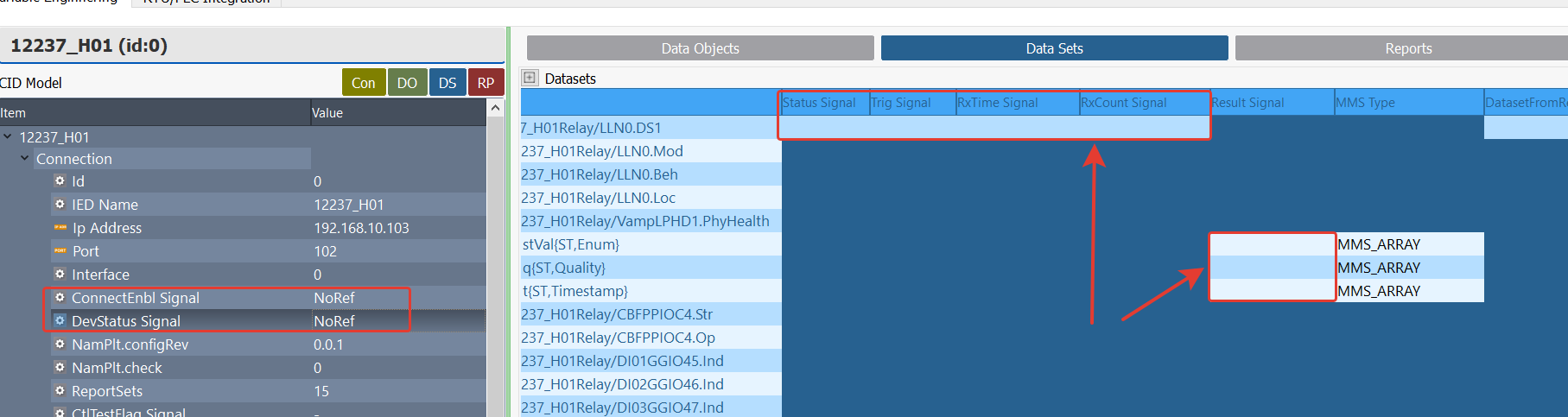
ConnectEnb Signal: To open and close the connection with the relay. (detailed in Data Object Read)
DevStatus Signal: To monitor the connection status. (detailed in Data Object Read)
Status Signal: Used to monitor the status of the reading operation. The block to be associated via Telediagram is selected. The possible values and their descriptions for this signal are as follows:
0: WAITING/FAIL, Waiting for request response or operation failed
1: OK, Request completed successfully.
2: MISMATCH, Operation failed due to incompatibility.
3: TIMEOUT, Operation failed due to timeout.
4: FAILED, Operation failed due to internal error.
100 and above: Operation failed due to library error. (Error code: status value - 100 can be calculated.)Trig Signal: The trigger block to be associated in Telediagram for reading data sets is selected.
RxTime Signal: Used to show the data reception time.
RxCount Signal: Used to track the number of data set receptions.
Result Signal: The value of the relevant data sets on the relay is read through this block. The block to be associated via Telediagram is selected.
MMS Type: Variable type. This section is automatically updated according to the data object selected in the project. (detailed in Data Object Read)
DatasetFromReportFlag Signal: Indicates whether the data set is received via the reporting mechanism.
Data Set Application Example
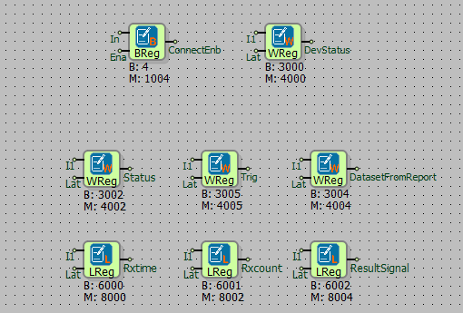
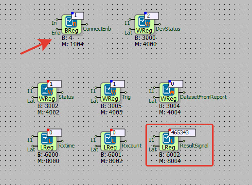
Open the Telediagram application and create a new project. The signals defined in MDV61850 Browser are mapped to the appropriate register type in Telediagram.
In this example, the following variables are selected:
- ConnectEnb Signal → Binary Register
- DevStatus Signal → Word Register
- Status Signal, Trig Signal, Data Set From Report → Word Register
- RxTime Signal, RxCount Signal → Long Register
- Result Signal → Long Register (A block is added from Telediagram to the Result Signal section based on the variable type specified in the MMS Type column.)
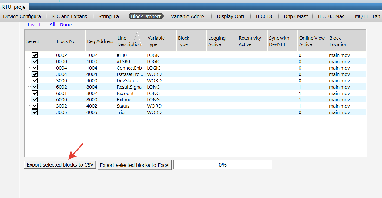
The blocks defined in Telediagram are exported in CSV format from the block properties table.
MDV61850 Browser is opened, and the RTU/PLC Integration section is accessed. The CSV file obtained from Telediagram is imported.
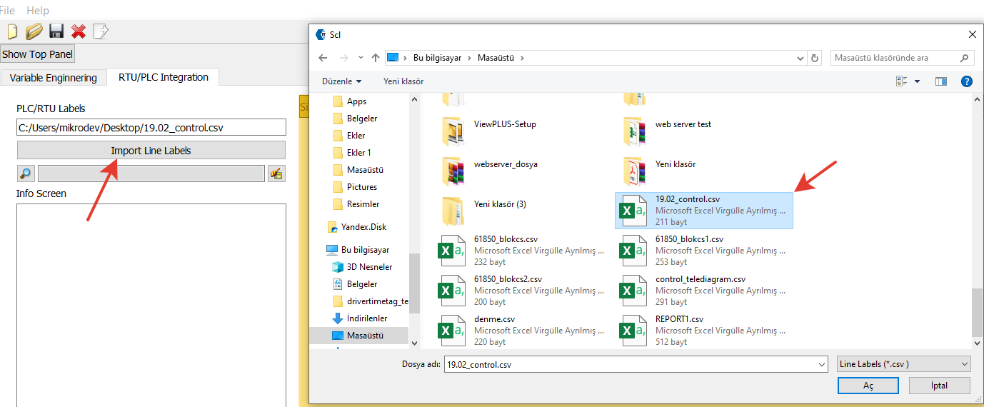
When the import process is completed, the information screen displays the properties of the blocks. On the right side of the screen, detailed information about the blocks is listed.
In MDV61850 Browser, the tag mapping process is performed using the following steps:
- Double-click on the relevant section where the tag should be mapped.
- In the Tag List window that appears, the available tags for mapping are displayed.
- Select the appropriate tag and map it to the corresponding section.
After completing the mapping process in MDV61850 Browser, the configuration can be exported in Excel format. From the File menu, select the "Export to Excel" option.
In the window that appears, select the file path where the Excel file will be saved and click the Save button.
The IEC 61850 table is opened in Telediagram, and the Excel file obtained from MDV61850 Browser is imported using the import tables (append) from excel option at the bottom of the table.

When the Excel file is imported, the IEC 61850 Table automatically populates with the blocks selected from the Browser.
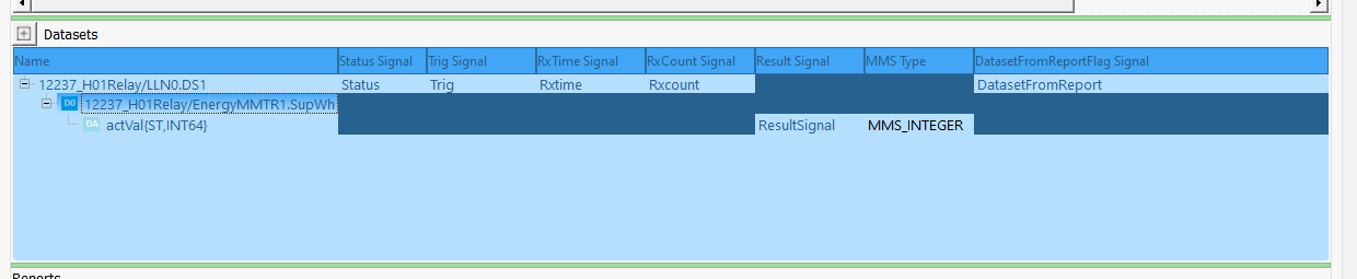
When these steps are completed, the necessary configuration for communication between the relay and RTU is finalized. Finally, the RTU project created in Telediagram is uploaded to the device, making the system ready for operation.
After completing the configuration with MDV61850 Browser and Telediagram, the following steps are applied to test whether communication between the RTU and the relay is successful:
- Connect to the RTU device via Telediagram and enable online monitoring. To initiate communication between the RTU and the relay, send the value 1 to the ConnectEnb block.
- Monitor the Dev Status block to check the communication status between the RTU and the relay. If the Dev Status block displays the value 2, communication has been successfully established.
- To read the data set value, send a trigger to the Trig block. The data set value is retrieved from the Result Signal block. The Status block is monitored to check whether the data set value has been successfully received.
Report Reading
In the IEC 61850 protocol, reports are used to read data sets without triggering them.
Note: To successfully read reports, both the data set and the corresponding reports must be selected in MDV61850 Browser.
MDV61850 Browser is opened from the Telediagram tools menu, and either a new project is created or a previously prepared project file is selected.
In the lower-left Reports section, the created reports are listed. The report to be read is added to the Reports table on the right by double-clicking it. It must be ensured that the DatasetRefPath of the added report in the Reports table matches the dataset name added to the Data Set Table.
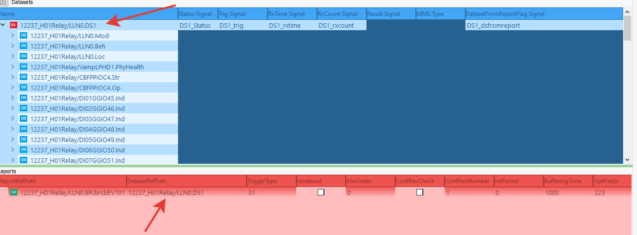
Report Ref Path: The file extension of the selected report.
Data Set Ref Path: The file extension of the data set to which the relevant report is linked.
Trigger Type: Determines under which trigger conditions the report will operate. When the Trigger Type column is double-clicked, the pop-up screen shown in Figure 45 opens.
- TRG_OPT_DATA_CHANGED: Send on data change.
- TRG_OPT_QUALITY_CHANGED: Send on quality change.
- TRG_OPT_DATA_UPDATE: Send when data is updated .
- TRG_OPT_INTEGRITY: Send periodically.
- TRG_OPT_GI: Send when a general interrogation request arrives.

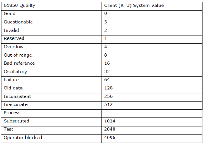
Note: The following table shows how the Quality values in the IEC 61850 protocol are mapped to the RTU (Client) system within the MDV61850 Browser. In the RTU system, each quality status is expressed by a specific integer value.
- IsIndexed: Determines whether the reports are indexed.
Indexed reports (Buffered Reports – BRCB) store past events and process them in a specific order.
Unindexed reports (Unbuffered Reports – URCB) transmit events only instantaneously.
If the IsIndexed value is 1, a Buffered Report is used.
MaxIndex: Determines the maximum index number for indexed reports. Determines the maximum number of events held when Buffered Reports (BRCB) are used. If the index value reaches the maximum, old records are deleted. For example, if there is a buffer memory for 1000 events, the oldest event is deleted, and the newly arrived event is recorded.
Conf Rev Check: Enables configuration revision control.
Conf Rev Number: Specifies the configuration revision number.
IntPeriod: Determines the reporting period of the report. If data will be sent periodically (if trigger type TRG_OPT_INTEGRITY is selected), the periodic sending time (in ms) should be entered in the Int Period column.
Buffering Time: This parameter determines how long buffered reports will store data. If BRCB is used, events are held in memory for a certain period. If Buffering Time is increased, it stores older events for a longer duration. If the buffer overflows, it can be manually cleared with the Purge Buffer Signal.
Opt Fields: Determines which additional fields the IEC 61850 reports will include. Report Time Stamp, ConfRev.
Enable Signal: The block to be associated via Telediagram to determine whether the report is enabled is selected.
Status Signal: The block to be associated via Telediagram to monitor the status of the report is selected. The possible values and their descriptions for this signal are as follows:
- INIT=0: Waiting for Enable Signal.
- REGISTER=1: Report activation is starting.
- WAITRCBVALUES=2: Report RCB read request sent, waiting for response.
- HASRCBVALUES=3: Report RCB read, activation process continues.
- WAITSETRCBVALUES=4: Report RCB updated, waiting for result.
- INSTALLED=5: Report installed, ready for report reception.
- ACTIVE=6: Report installed and at least one report received.
- FAILEDINIT=7: Report activation failed. The device will retry after 60 seconds.
- FORCETOCLOSE=8: Report deactivation request received, deactivation started.
- FORCETOCLOSE_WAITDISABLE=9: Deactivation process continues.
- FORCETOCLOSE_UNRESERVE=10: Reservation for deactivation is being removed.
- FORCETOCLOSE_WAITUNRESERVE=11: Deactivation process is completing.
Note: The ACTIVE (6) value indicates that the report is running successfully and at least one report has been received.
The FAILEDINIT (7) value indicates that the report activation process failed and the device will try again after 60 seconds.
The FORCETOCLOSE (8-11) values indicate that the report is in the deactivation process.
Send GI Signal: If GI is selected as the Trigger Type of the report, a trigger signal must be assigned to the Send GI Signal input. When a rising signal (1) is applied to this input, a General Interrogation (GI) request is triggered, and the report is sent.
Purge Buffer Signal: Used to clear the buffer memory in the report section in case of buffer overflow. If a buffer overflow occurs, the user can manually clear the buffer memory by applying a rising signal (1) to the input of the Telediagram block associated with the Purge Buffer Signal.
Ignored Report: Determines how the client handles report control block configuration revision mismatches. If the report control block configuration revision is incompatible, the report is not processed and is ignored. The number of reports ignored for this reason can be tracked via the IgnoredReportCount signal.
Note: When only a report is selected, an exclamation mark (!) appears in the Data Set Path section. For the report to work correctly, the relevant Data Set must also be added to the browser.
Data Set Not Selected;
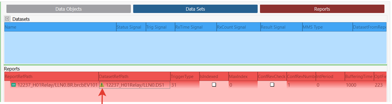
Data Set Selected;
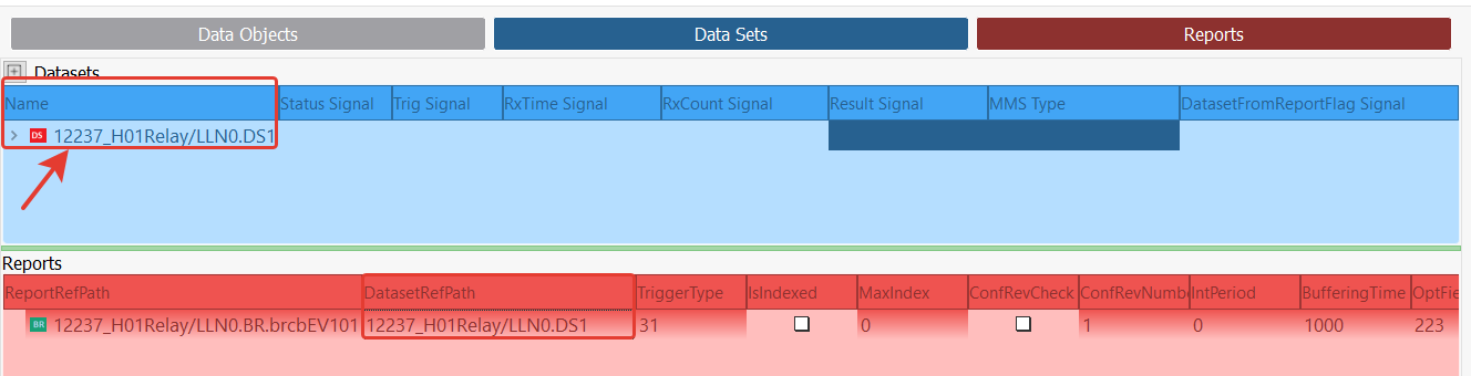
Note: Make sure that the DatasetRefPath value of the report added to the Reports table is the same as the dataset added to the Data Set Table.
Report Reading Application Example
The signals defined in MDV61850 Browser are associated with appropriate register types in Telediagram. In the example described here, the following variables have been selected:
Blocks for connection with the relay:
- ConnectEnb Signal → Binary Register
- DevStatus Signal → Word Register
Blocks in the dataset table:
- Status Signal, Trig Signal, Data Set From Report → Word Register
- RxTime Signal, RxCount Signal → Long Register
- Result Signal → Long Register (A block is added from Telediagram to the data signal section according to the variable specified in the MMS Type field.)
Blocks in the report table:
- Enable Signal → Binary Register
- Status Signal, Send GI Signal, Purge Buffer Signal, Ignored Report Count → Word Register
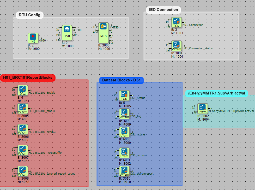
The blocks defined in Telediagram are exported to CSV format from the block properties table.
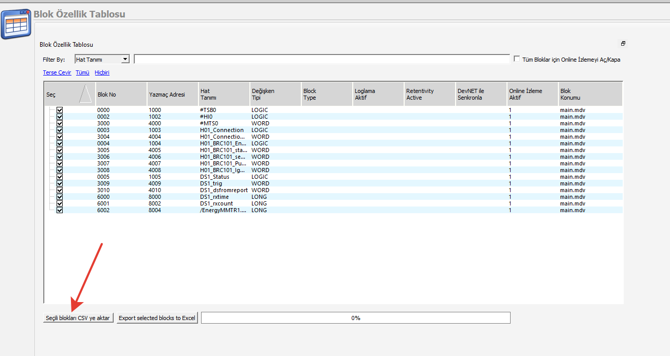
The MDV61850 Browser is opened, and the RTU/PLC Integration section is accessed.
The CSV file obtained from Telediagram is imported.

Once the import is complete, the information screen displays the properties of the blocks. Detailed information about the blocks is listed on the right screen.
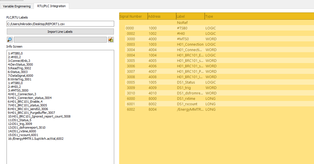
In MDV61850 Browser, the tags must be matched. The relevant section where the tag will be assigned is double-clicked. In the opened Tag List window, the tags to be matched with the relevant section are displayed.
The appropriate tag is selected and matched with the corresponding section.
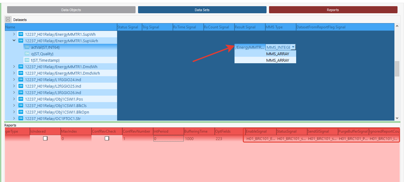
After the matching process is completed in MDV61850 Browser, the configuration can be exported in Excel format. From the File menu, the Export to Excel option is selected.

In the opened window, the file path for saving the Excel file is selected, and the Save button is clicked.
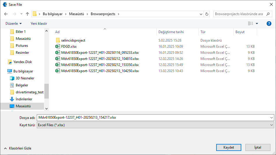
In Telediagram, the IEC 61850 table is opened, and the Excel file obtained from MDV61850 Browser is imported using the "import tables (append) from Excel" option located at the bottom of the table.

Once the Excel file is imported, the IEC 61850 Table automatically displays the blocks selected from the Browser. This ensures that all required signals and configurations are correctly transferred to Telediagram without manual input.
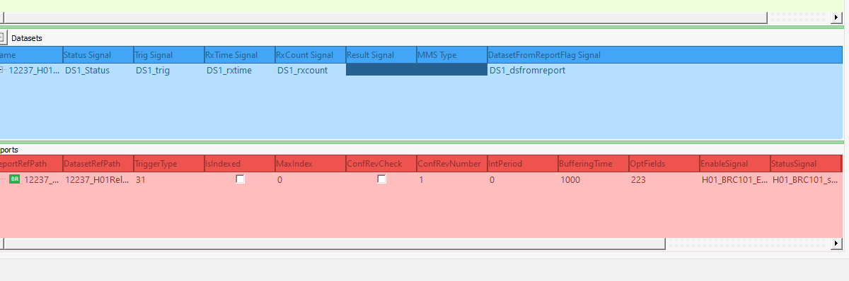
When these steps are completed, the necessary configuration for communication between the relay and the RTU is finalized. This step is critical because it establishes the signal mapping required for successful data exchange.
Finally, the RTU project created in Telediagram is uploaded to the device, making the system ready for operation. Ensuring a successful upload is important to avoid configuration mismatches.
After completing the configuration using MDV61850 Browser and Telediagram, the following steps are applied to test whether communication between the RTU and the relay is successful:
- Connect to the RTU device via Telediagram and open online monitoring. This allows real-time observation of data exchange.
- To start communication between the RTU and the relay, set the ConnectEnb block to 1. This enables the communication link. Monitor the Dev Status block to check the communication status between the RTU and the delay. If the Dev Status block shows the value 2, communication has been successfully established. Any other value might indicate a configuration issue or connection failure.
- When the Report Enable tag is set to 1, the Report Status and Data Set From Report blocks should receive the value 6. This confirms that the report mechanism is functioning properly.
- In the RxTime Signal, the dataset value's read time should be displayed in epoch time. This ensures that timestamps are correctly processed. The Result Signal should display the current value of the dataset. Any discrepancies in the expected values might indicate issues in data mapping or communication delays.
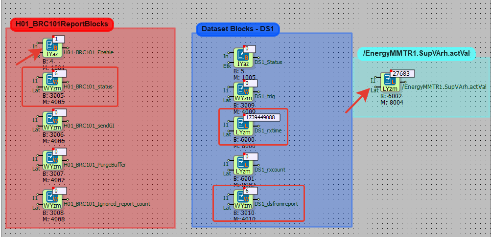
By following these steps, the successful communication between the RTU and the relay can be verified, ensuring that the system is correctly configured and operational.
MOD-C Table Panel
Add Meter
Adding Meter, adding OBIS Code, adding programming mode command are done in this section.
Note: For Makel Meter ; Meter Serial Prefix: MSY
Note: If the serial number is less than 8 digits, it is necessary to complete the serial number to 8 digits. For this, it is necessary to write 0 in the counter serial prefix section until the number of missing digits.
Note: Port 1 : RS485 , Port 2 : RS232 , Protocol : Mode C
| Meter | Makel | Köhler | EMH |
|---|---|---|---|
| Starting Baudrate | 300 | 300 | 19200 |
| MODC Baudrate | 9600 | 9600 | 19200 |
| Data Bit | 7 | 7 | 7 |
| Parity Bit | Even Parity | Even Parity | Even Parity |
| Stop Bit | 1 | 1 | 1 |
| Readout Type | 0 | 0 | 0 |
Add OBIS Codes
Add Programming Mode
Reading OBIS Codes Outside The Service List
First of all, we enter the meter number we want to read and the OBIS codes we want to read on it.
We enter the OBIS codes, outside the service list.
For example; 2.8.0 Obis code.
Add Programming Mode Command to the Selected Meter.
We enter the code we want to read.
Note: An example is given for the Köhler brand meter. You can request the codes suitable for your device from your meter manufacturer.
Load Profile Reading
Choose the Meter.
Add Programming Mode Command to the Selected Meter
We add the commands one after the other.
01 52 32 02 31 32 38 2e 31 30 2e 30 30 30 30 28 29 03 5a  // [ Read Load Profile Index Information ]
01 52 32 02 31 32 38 2e 35 31 2e 31 28 46 46 46 46 29 03 46 // [ Read values defined in load profile MODC OBIS Codes section ]
01 42 30 03 71  // [ Ends the load profile reading process ]
- We add the data we want to see the load profile values, from the Add OBIS Code to the Selected Meter.
Load Profile Codes:
for Ael tf 19/20/21 ;
#P1#,2,0,8,0; ----> Load Profile Index Value (DECIMAL)
#P1#,2,20,8,-3; ----> +T value (FLOAT)
#P1#,2,28,8,-3; ----> -T value (FLOAT)
#P1#,2,36,8,-3; ----> +Ri value (FLOAT)
#P1#,2,44,8,-3; ----> +Rc value (FLOAT)
#P1#,2,52,8,-3; ----> -Ri value (FLOAT)
#P1#,2,60,8,-3; ----> -Rc value (FLOAT)
#P1#,2,8,10,0; ----> Load profile record date epoch (DATETIME)
for Makel c410, c500 ;
#P2#,Active ----> +T value ( FLOAT )
#P2#,Capacitive  ----> +Rc value  ( FLOAT )
#P2#,DateTime ----> Load profile record date epoch   (DATETIME)
#P2#,I1 ----> IrmsA value  ( FLOAT )
#P2#,I2 ----> IrmsB value ( FLOAT )
#P2#,I3 ----> IrmsC value ( FLOAT )
#P2#,Inductive  ----> +Ri value   ( FLOAT)
#P2#,V1 ----> VrmsA value ( FLOAT )
#P2#,V2 ----> VrmsB value ( FLOAT )
#P2#,V3 ----> VrmsC value ( FLOAT )
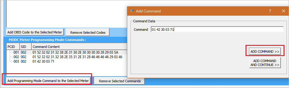
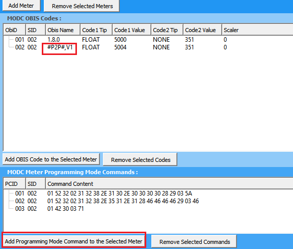
Rest API Configuration
Defining REST API servers
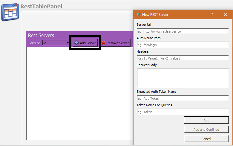
The first thing to do is to define some parameters related with the REST API Server. On the RestTablePanel, click on Add Server button to open New Rest Server Dialog. On the dialog you will be asked the following parameters:
Server URL
The root url of the server which serves the API.
Auth Route Path
If the API requires authentication, set the path for the authentication path here. Do not use the root url here, only the relative path should be inserted(eg : /api/login ) .
Headers
If you need to use any special headers during authentication process insert them in a comma separated key/value format(eg: Key1 : Value1, Key2 : Value2) .
Request Body
If you need to use a request body during authentication process insert it here.
Expected Auth Token Name
After authentication, if the server sends a token for authentication , insert the name used for token data in here.
Token Name For Queries
After you get the token data, you may need to use a different token name on your API calls. Write here the token key name to be used.
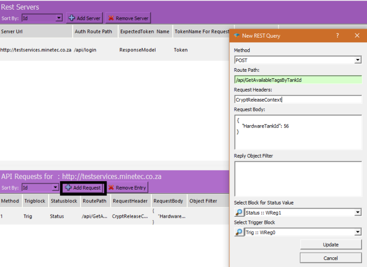
Add new REST Request Object
After you add a Rest Server, now you can start to add API request definitions on that server. Click on the Rest Server to which you will add the request and click Add Request button. You need to insert the following parameters on the dialog
Method
The HTTP method to be used for the request. It could be a POST, GET, PUT or DELETE request.
Route Path
The route path of the request. Start with "/" and do not use the root URL here (eg: /api/GetTankLevel ).
Request Body
If you need to use a request body during the API call insert it here.
Reply Object Filter
After you send the API request the server will send you a reply in JSON form. You need to use a filter to be able to get the relevant data from this JSON object. Please see the following example to be able to get the data in different forms:
The example reply from the server is:
  {
    "Message": null,
    "ResponseModel": {
        "AvailableTags": [
            {
                "CanTakeFuelOutside": false,
                "CurrentMachineHours": 20,
                "THPT": 85,
                "TagNumber": "TestTag000000001",
                "UnitType": "Hour",
                "VehicleTankCapacity": 300
            },
            {
                "CanTakeFuelOutside": false,
                "CurrentMachineHours": 102,
                "THPT": 85,
                "TagNumber": "TestTag000000002",
                "UnitType": "Hour",
                "VehicleTankCapacity": 300
            }
        ],
        "ServerDateTime": "14.02.2021 22:01:44"
    },
    "Type": "S"
}
Example Filters
• To be able to get the VehicleTankCapacity of the first element of the AvailableTags array and write it into a block with number 6000 :
ResponseModel.AvailableTags[0].VehicleTankCapacity ,6000;
• Get all the CurrentMachineHours in the AvailableTags array and write them into a table block with number 6000:
ResponseModel.AvailableTags[].CurrentMachineHours , 6000;
• Find the object with TagNumber is equal to "TestTag000000002" in the array and get the VehicleTankCapacity value of this object and write that value into the block with block number 6000:
ResponseModel.AvailableTags[].TagNumber(TestTag000000002).VehicleTankCapacity, 6000;
Select Block for Status Value
The return code of the API request will be written into this block
Select Trigger Block
Whenever this block is enabled the API request will be sent to server.
Telediagram License
Installing the License File
To get a valid license please send your "hardware id" to [email protected].
To find out your hardware id; after you download and install Telediagram application, go to the "bin" directory of the application and run "license_user.exe" .
Before running "license_user.exe" make sure that no "usb stick" or "external harddrive" is connected on your computer since that may change your hardware ID.
After you receive a valid "tlicense.dat" file, copy this file into the "bin" directory of Telediagram application
The licence will automatically be loaded when you restart the Editor