DM500 Hardware Manual
Panel Installation Information
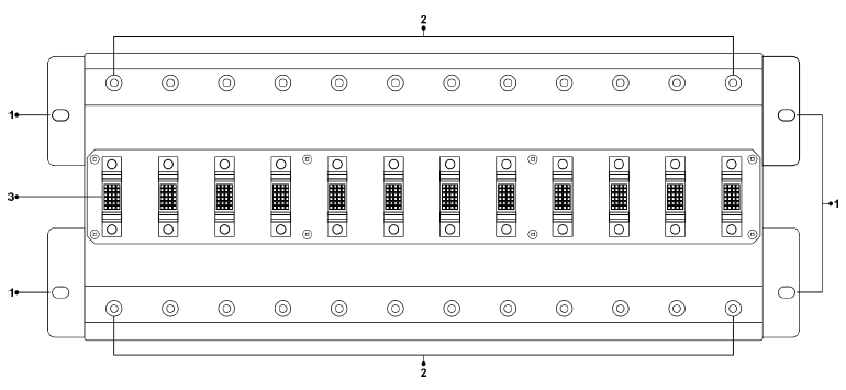
Panel Installation
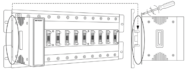
Rack Panel Mountage
The FCI connector output on the back of the device is plugged into the slots on the panel. Screws are inserted into the screw inlets located on both sides of the slots with a screwdriver and fixed. While installing the devices, make sure that the device is fully seated in the slots on the panel.
Rack Panel Demountage
The screws attached to the slots on the panel are removed with the help of a screwdriver. The FCI connector output on the back of the device is pulled out from the slots on the panel. While disassembling the device, care must be taken not to damage the slots.
DM500 General Information
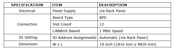
BP0 Rack Panel Board Type Physical Interfaces

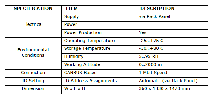
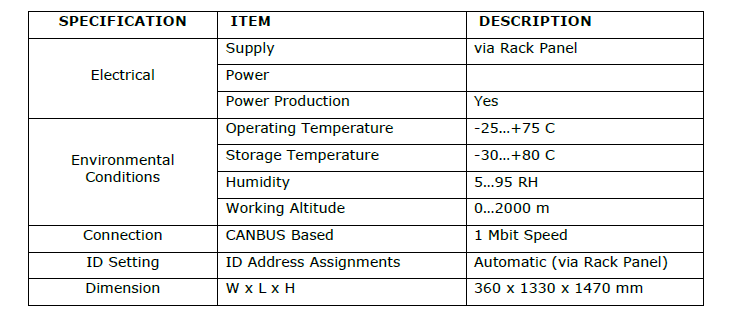
General Device Specifications
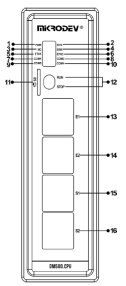
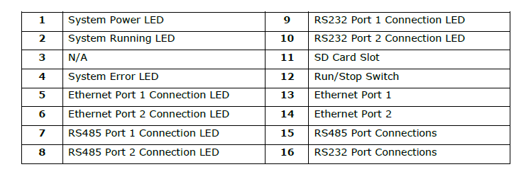
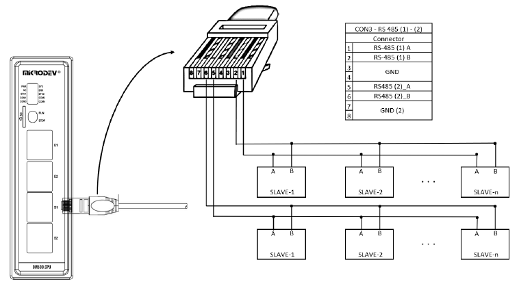
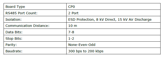
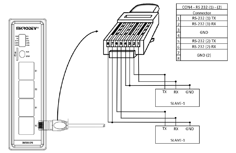
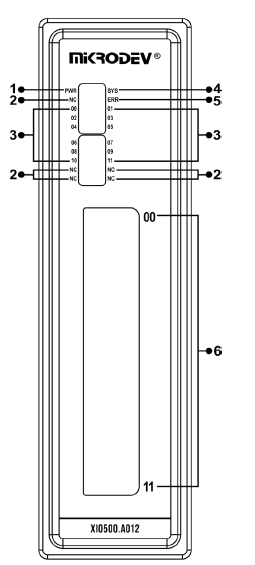
CP0 CPU Board Type Physical Interfaces
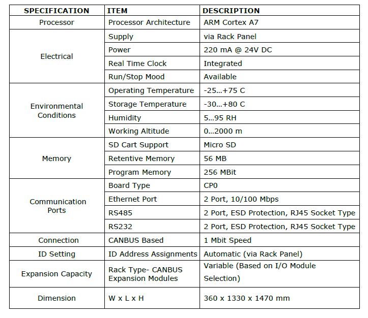
General Device Specifications
Connection Diagrams
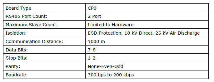
RS485 Serial Port
RS232 Serial Port
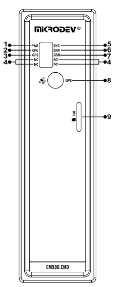
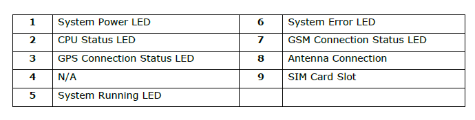
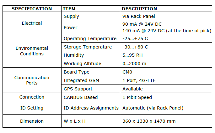
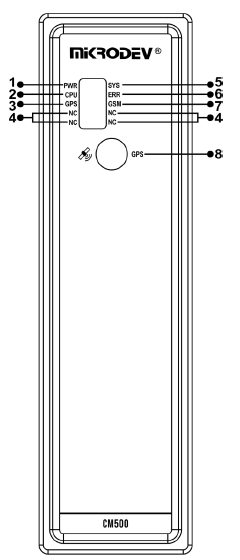
CM0 Communication Board Type Physical Interface
General Device Specifications
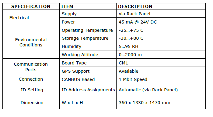
CM1 Communication Board Type Physical Interface

General Device Specifications
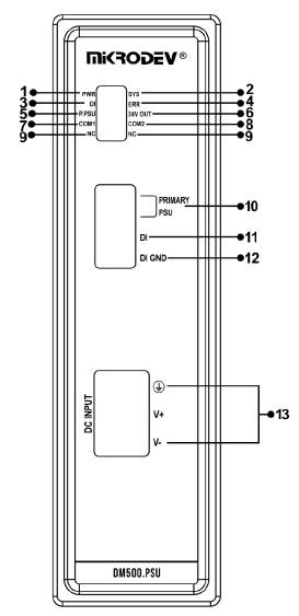
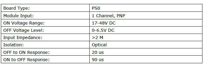
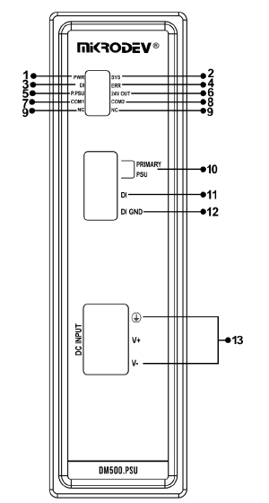
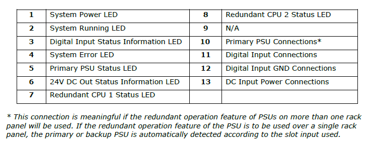
PS0 PSU Board Type Physical Interface
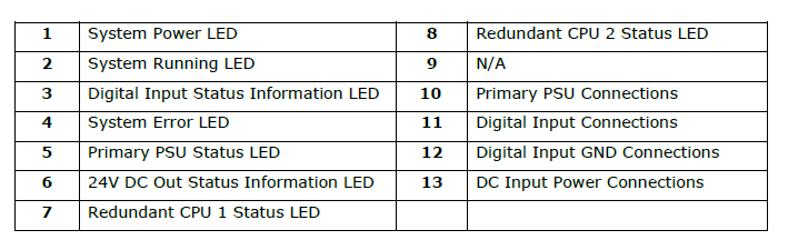
General Device Specifications
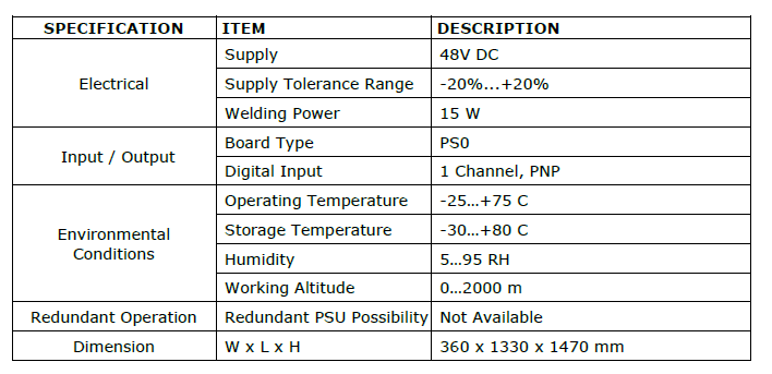
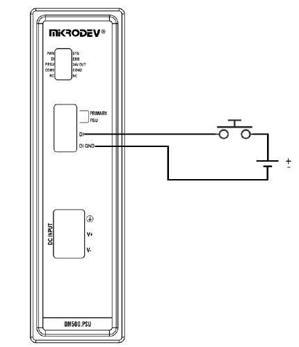
Connection Diagrams
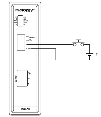
Supply Connection
Digital Inputs
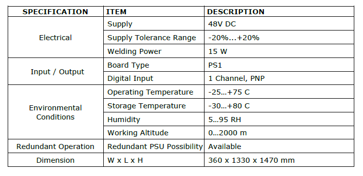
PS1 PSU Board Type Physical Interface
General Device Specifications
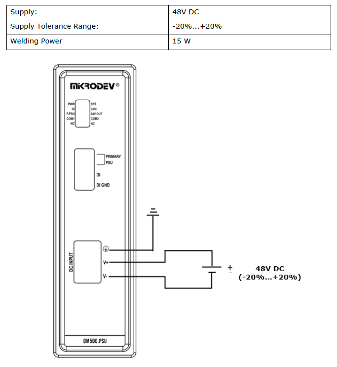
Connection Diagrams
Supply Connection
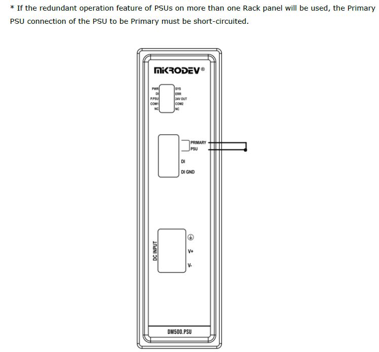
Redundant Connection
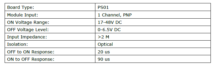
Digital Inputs
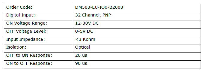
IO0 Digital Input (32 Digital Inputs) Board Type Expansion Modules Physical Interface
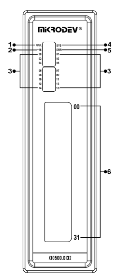
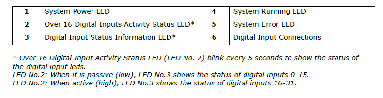
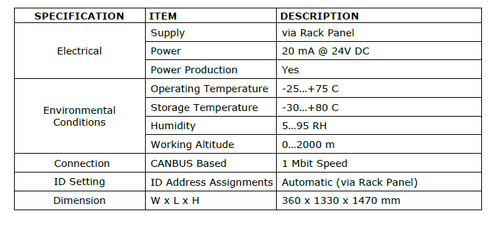
General Device Specifications
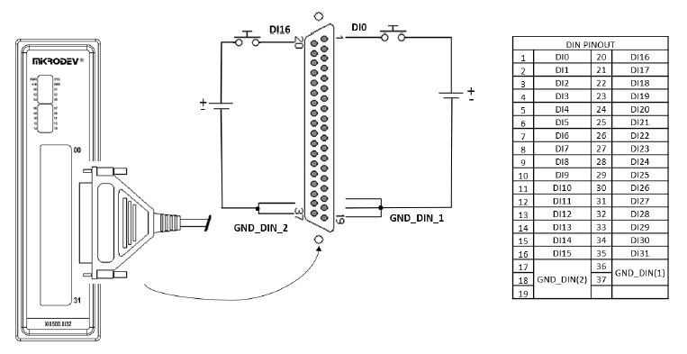
Connection Diagrams
Digital Inputs
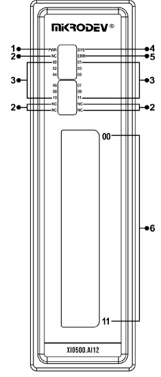
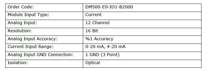
IO1 Analog Input (12 Analog Inputs) Board Type Expansion Modules Physical Interface

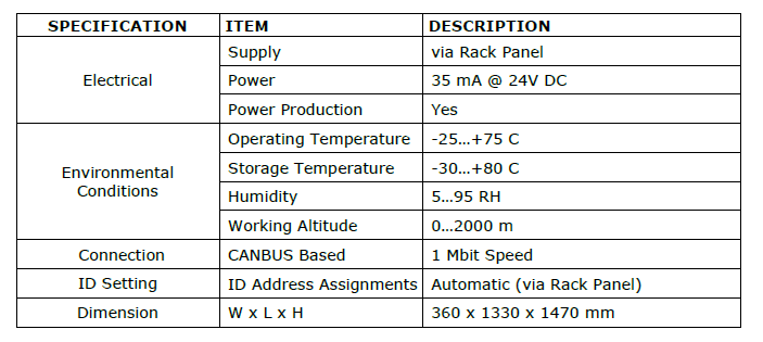
General Device Specifications
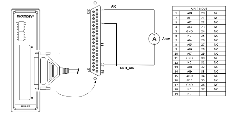
Connection Diagrams
Analog Inputs
IO2 Digital Output (32 Digital Outputs) Board Type Expansion Modules Physical Interface
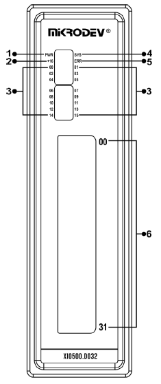
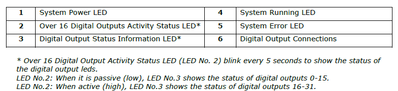
General Device Specifications
Connection Diagrams
Digital Outputs
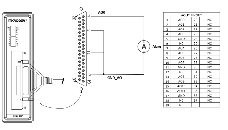
IO3 Analog Output (12 Analog Outputs) Board Type Expansion Modules Physical Interface

General Device Specifications
Connection Diagrams
Digital Outputs