DALI Application Notes
DALI PROTOCOL
DALI DALI2 Protocol General Information
The international standard of DALI (Digital Addressable Lighting Interface) technology is IEC 62386.
DALI provides bidirectional data communication for lighting systems. It is a widely used automation system especially in commercial buildings. Thanks to the DALI protocol; systems such as ballasts, drivers, control units, lighting fixtures and emergency lighting fixtures become controllable from a single point.
DALI-2 has been developed by adding numerous new commands and features to the original DALI standard.
DALI Expansion Module Wiring Diagram
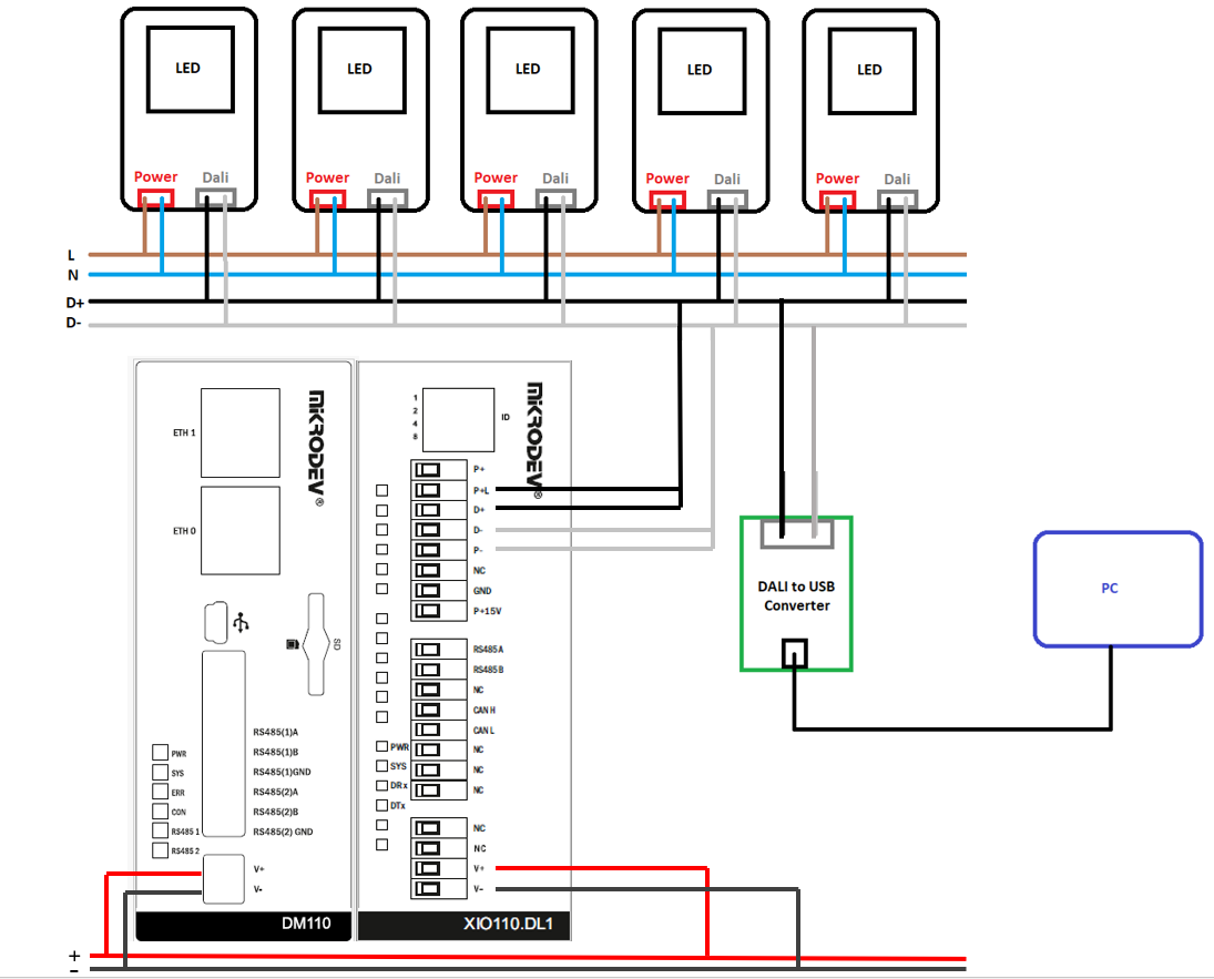
Note: The DALI line expansion module must be powered with a 15V 300mA output; otherwise, communication will not be established.
In order to use the DALI power supply in our product, a bridge connection must be made in the terminal connections as seen in the diagram.
IMPORTANT! Before starting the process with the Mikrodev DALI Expansion Module, a USB-DALI Converter must be configured. Configuration; addressing, grouping, power-on, min, max level selections and scene selections. PLC program is written according to these addresses. You can refer to the DALI Configurator document for configuration details.
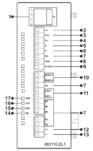
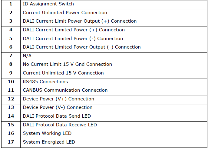
GDA Board Type (1 DALI Port) Physical Interfaces
DALI Block
Block Connection
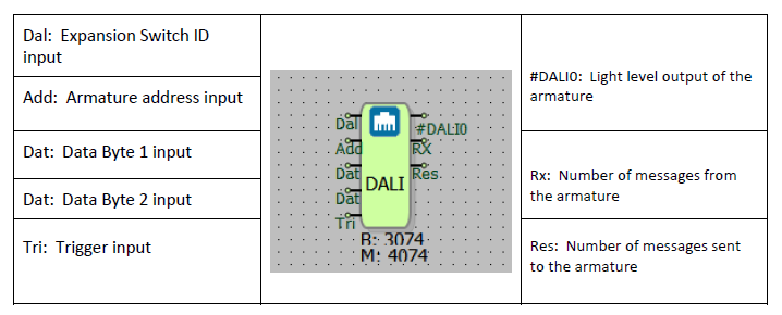
Block Connection Explanation
It is used to send data packets to the DALI line that cannot be sent from the DALI manager block.
Inputs:
- Dali Bus: It is the input for the Expansion Switch ID.
- Address Byte: It is the input for the armature address.
- Data Byte 1: It represents the 1st byte of the data packet to be sent to the DALI line. (The value is sent in decimal format.)
- Data Byte 2: It represents the 2nd byte of the data packet to be sent to the DALI line. (The value is sent in decimal format.)
- Trig: This is the trigger input of the block. When a trigger is applied here, the data packet intended to be sent through the block is transmitted to the DALI line.
Outputs:
- DALI0: It provides the light level of the armature.
- Rx: It is number of messages from the armature
- Tx: It is the number of messages sent to the armature.
Custom Settings
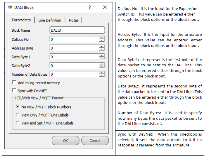
Block Explanation
The DALI block allows you to send data packets directly to armatures. Data packets that cannot be sent from the DALI Manager block can be parsed into bytes and transmitted to the DALI line through this block, enabling remote control of armatures. You need to enter the decimal equivalents of the data packet you want to send into the data byte sections.
Before starting operations with the Mikrodev DALI Expansion Module, configuration must be performed using a USB-DALI Converter. The configuration should include addressing, grouping, power-on, minimum and maximum level selections, and scene selections. The PLC program is written based on these addresses.
Note: Data packets sent from DALI switching elements with DALI-2 support can be read via RTU. For this purpose, the DALI block is used.
Example: Suppose a DALI switching element is connected at address 0 on DALI bus number 0. To read the data packet from this element, the special settings of the DALI block should be configured as follows:
Dalibus No: 0 (The switch ID of the DALI expansion module to which the relevant switching element is connected should be entered.)
Address Byte: 0 (The address number to which the switching element is connected should be entered.)
Data Byte1: 255 (To read the data packet sent from the switching element, the value 255 should be entered here.)
Data Byte2: 255 (To read the data packet sent from the switching element, enter the value 255 here.)
Sample Application


In the example application, a DALI switching element is connected to DALI bus number 0 at address 0. When the switch is in the open position, a value of 0 is read from the Rx output of the DALI block, and when it is in the closed position, a value of 255 is read. Based on these values read from the switching element, the DALI armatures in the field are controlled.
DALI Manager Block
Block Connection
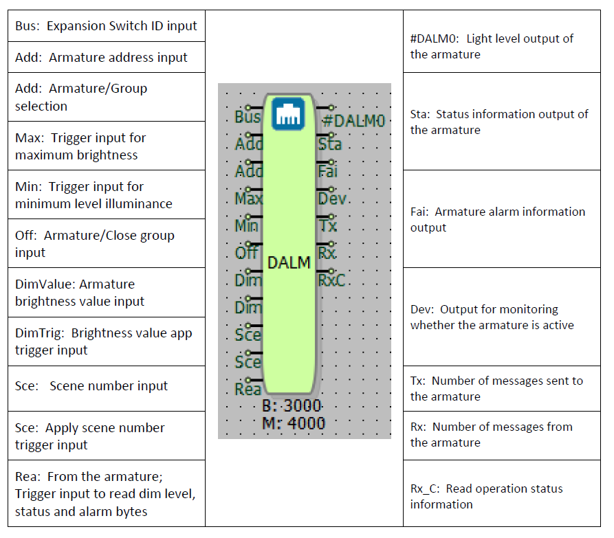
Block Connection Explanation
Inputs:
- Bus Id: Expansion Switch ID entry.
- Address: It is the armature address input.
- Address Type: If this input is 0, it is treated as a armature, and if it is 1, as a group address.
- Max Level: When a trigger is applied to this input, the armature /group gives maximum level illumination.
- Min Level: When a trigger is applied to this input, the armature /group gives a minimum level of illumination.
- Off: When this input is triggered, armature/group closes.
- Dim Value: Brightness value between 85-254 is input to the armature.
- Dim Trig: When this input is triggered, it applies the value applied to the "Dim Value" input to the armature.
- Scene No: Scene number entry. A value between 0-15 is entered.
- Scene Trig: When this input is triggered, it sends the value applied to the “Scene No” input to the DALI line and the scene application is started.
- Read Trig: From the armature; Trigger is given to read dim level, status and alarm bytes. (ADDRESS TYPE MUST BE 0!)
Outputs:
- Actual Level: Returns the luminous level of the armature.
- Status Byte: It contains the status information of the armature. By doing bit parsing, we can obtain the following information;
• Bit 0: General alarm. 0 = No Error, 1 = Error
• Bit 1: Lamp Fault. 0 = No Error, 1 = Error
• Bit 2: Lamp Status. 0 = Off, 1 = On
• Bit 3: Limit Error. 0 = No Error, 1 = If value other than Min/Max level is entered, it will be 1.
• Bit 4: Fade Operation. 0 = No Fade operation 1 = Fade operation on.
• Bit 5: Reset status. 0 = Not in reset state, 1 = All variables (dim, fade, ..etc) are in initial state.
• Bit 6: Address Error. 0 = Addressing done, 1 = Addressing not done.
• Bit 7: Energy Cycle. 0 = Normal operation, 1 = 1 when first energized, decreases to 0 at next dim level changes etc.
fade: It makes the armature flash slowly like an analog ramp, for example, it is the process of going from dim level 0 to 100 in 10 seconds. This 10 sec should be specified in the configuration, we do not do any extra operations on the plc. - Fail Status Byte: It contains the alarm information of the armature. By doing bit parsing, we can obtain the following information;
• 0. Bit: Led short circuit
• 1. Bit: Led open circuit
• 2. Bit: Load reduction
• 3. Bit: Load increase
• 4. Bit: Overcurrent protection
• 5. Bit: Thermal shutdown
• 6. Bit: Thermal overload
• 7. Bit: Reference Error - Device Status: It will be 0 when the read trigger comes, if there is a response from the armature, it will be 1, this timeout value can be adjusted with the off delay block and it can be monitored whether the armature is active or not.
- Tx: Number of messages sent to the armature
- Rx: Number of messages from the armature
- Rx Complete: It becomes 0 during the read operation and 1 when the read operation is finished.
Custom Settings
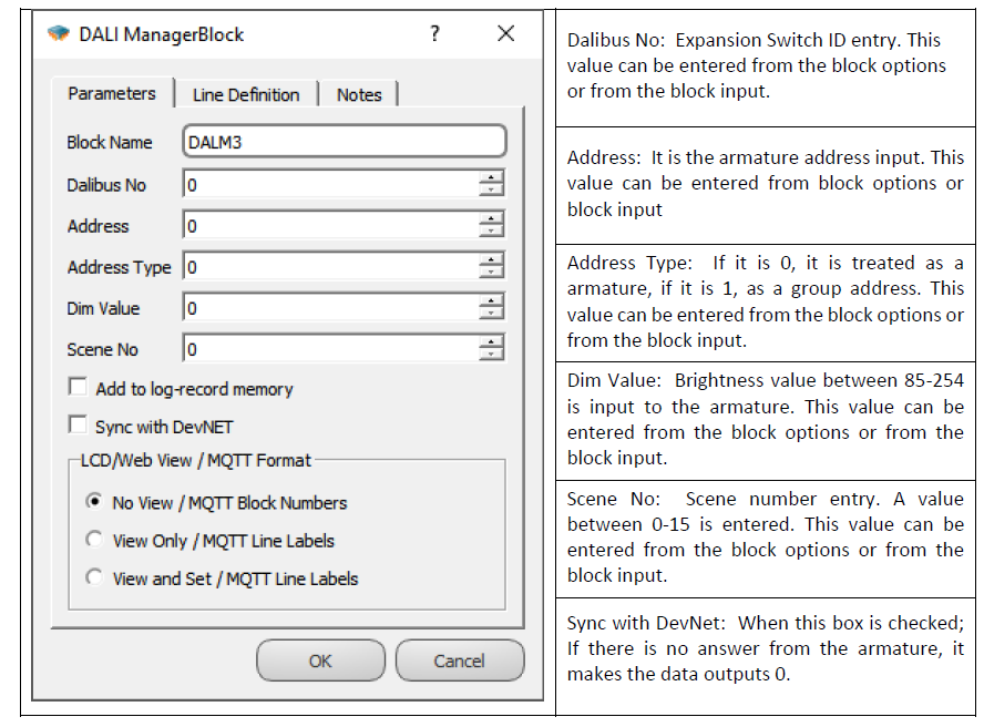
Block Explanation
DALI Manager block provides remote access to armatures or groups. Thanks to the DALI Manager block, we can adjust the armature brightness, read the light level of the armetures in the field, armature status information and armature error information from the block outputs.
Before starting the process with the Mikrodev DALI Expansion Module, a USB-DALI Converter must be configured. Configuration; addressing, grouping, power-on, min, max level selections and scene selections. PLC program is written according to these addresses.
You can refer to the DALI Configurator document for configuration details.
Sample Application
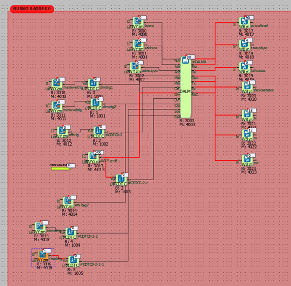
In the example application, a dim value of 90 was sent to the armature at address 0, connected to the Switch ID 0 input of the DALI expansion module, using the DALI manager block.
When the Read trig input was triggered, the DALI manager block's output read the dim value of 90.
DALI Manager Block 2
Block Connection
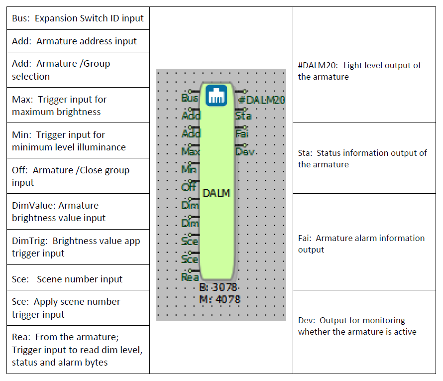
Block Connection Explanation
Inputs:
- Bus Id: Expansion Switch ID entry.
- Address: It is the armature address input.
- Address Type: If this input is 0, it is treated as a armature, and if it is 1, as a group address.
- Max Level: When a trigger is applied to this input, the armature /group gives maximum level illumination.
- Min Level: When a trigger is applied to this input, the armature /group gives a minimum level of illumination.
- Off: When this input is triggered, armature/group closes.
- Dim Value: Brightness value between 85-254 is input to the armature.
- Dim Trig: When this input is triggered, it applies the value applied to the "Dim Value" input to the armature.
- Scene No: Scene number entry. A value between 0-15 is entered.
- Scene Trig: When this input is triggered, it sends the value applied to the “Scene No” input to the DALI line and the scene application is started.
- Read Trig: From the armature; Trigger is given to read dim level, status and alarm bytes. (ADDRESS TYPE MUST BE 0!)
Outputs: Updates when read trig is applied.
- Actual Level: Returns the luminous level of the armature.
- Status Byte: It contains the status information of the armature. By doing bit parsing, we can obtain the following information;
• Bit 0: General alarm. 0 = No Error, 1 = Error
• Bit 1: Lamp Fault. 0 = No Error, 1 = Error
• Bit 2: Lamp Status. 0 = Off, 1 = On
• Bit 3: Limit Error. 0 = No Error, 1 = If value other than Min/Max level is entered, it will be 1.
• Bit 4: Fade Operation. 0 = No Fade operation 1 = Fade operation on.
• Bit 5: Reset status. 0 = Not in reset state, 1 = All variables (dim, fade, ..etc) are in initial state.
• Bit 6: Address Error. 0 = Addressing done, 1 = Addressing not done.
• Bit 7: Energy Cycle. 0 = Normal operation, 1 = 1 when first energized, decreases to 0 at next dim level changes etc.
fade: It makes the luminaire flash slowly like an analog ramp, for example, it is the process of going from dim level 0 to 100 in 10 seconds. This 10 sec should be specified in the configuration, we do not do any extra operations on the plc. - Fail Status Byte: It contains the alarm information of the armature. By doing bit parsing, we can obtain the following information;
• 0. Bit: Led short circuit
• 1. Bit: Led open circuit
• 2. Bit: Load reduction
• 3. Bit: Load increase
• 4. Bit: Overcurrent protection
• 5. Bit: Thermal shutdown
• 6. Bit: Thermal overload
• 7. Bit: Reference Error - Device Status: It will be 0 when the read trigger comes, if there is a response from the armature, it will be 1, this timeout value can be adjusted with the off delay block and it can be monitored whether the armature is active or not.
Custom Settings
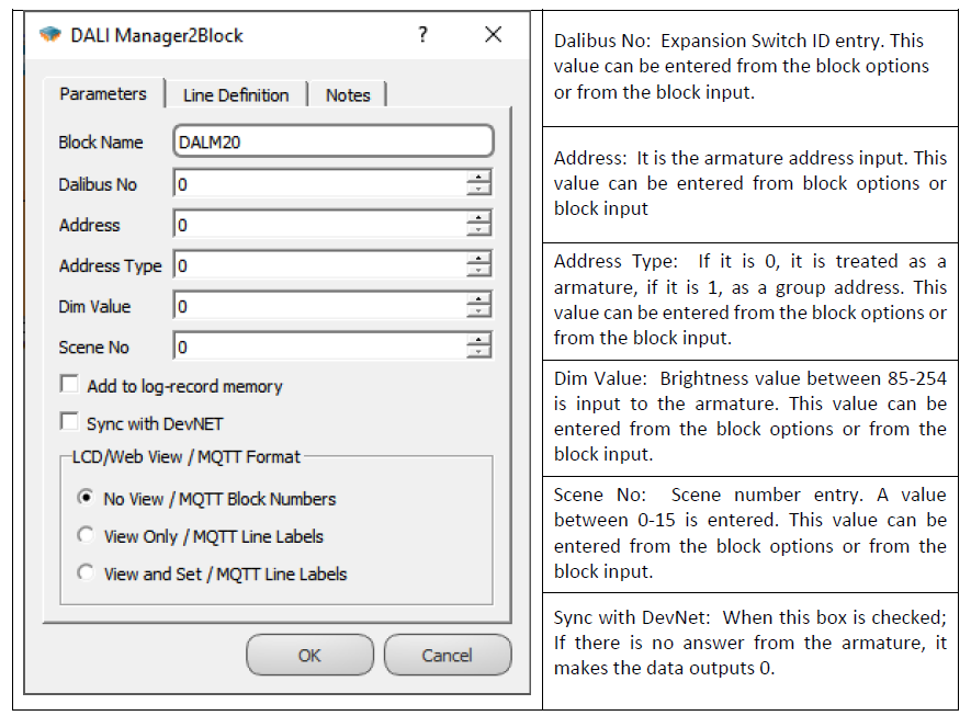
Block Explanation
DALI Manager block provides remote access to armatures or groups. Thanks to the DALI Manager block, we can adjust the armature brightness, read the light level of the armatures in the field, armature status information and luminaire error information from the block outputs.
Before starting the process with the Mikrodev DALI Expansion Module, a USB-DALI Converter must be configured. Configuration; addressing, grouping, power-on, min, max level selections and scene selections. PLC program is written according to these addresses.
You can refer to the DALI Configurator document for configuration details.