WEB SERVER User Manual
PC IP CONFIGURATION SETTINGS
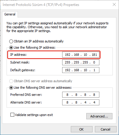
To access the DM50 Web Server interface, the computer's IP address must first be on the same network as the IP address of the device to be connected to. If they are not on the same network, access to the DM50 Web Server interface will not be possible from the PC. For this, the following instructions should be followed:
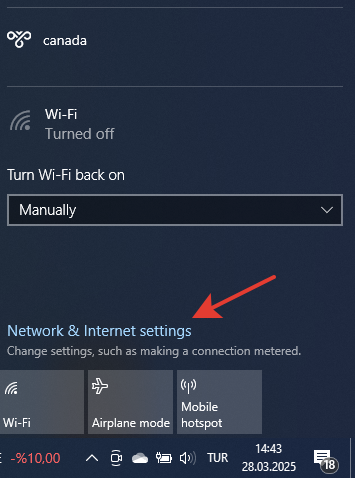
- Click on the internet connection icon located in the bottom right corner. Open Network & Internet settings.
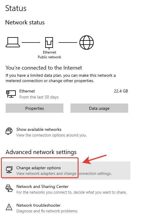
- In the Advanced network settings section, click on Change adapter options.
- Double-click on Ethernet -> Properties -> Internet Protocol Version 4 (TCP/IPv4).
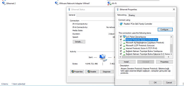
- On the Internet Protocol Version 4 (TCP/IPv4) Properties page, click on "Use the following IP address" and "Use the following DNS server addresses" options and manually configure a static IP address within the same subnet as the Router, then click "OK".
OPENING BLOCKS FROM TELEDIAGRAM PROJECT ON WEB SERVER VIEW
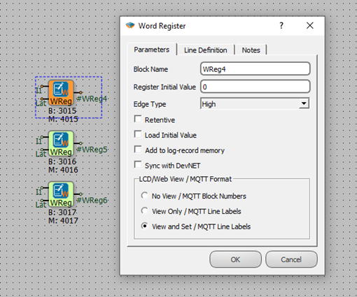
For the blocks in the Telediagram project to be monitored via the web server interface and for values to be sent to the blocks, the Web View options in the block's special settings must be checked.
No Monitoring: Blocks with this option checked will not be monitored via the web server interface.
Monitoring Only: Blocks with this option checked can only be monitored via the web server interface, values cannot be set for these blocks.
Monitoring and Modification: Blocks with this option checked can be both monitored and have their values set via the web server interface.
The project to be loaded onto the DM50 device must first be opened via the Telediagram program. The Web View options of the blocks to be monitored from the web server interface must be checked in the block's special settings.
Note: If the Web View feature of the relevant blocks is not activated via Telediagram, no blocks can be accessed from the web server interface.
ACCESSING THE DM50 WEB SERVER INTERFACE
To log in to the DM50 Web Server Interface, the following instructions should be followed:
Open any internet browser on your computer.
In the URL section, enter any Ethernet IP address of the device to be connected to (default: https://192.168.2.200).

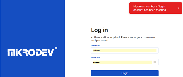
After pressing Enter, the user login screen shown in Figure 2 will appear. The default username and password should be entered in the Username and Password sections.
Default Username: admin
Password: admin

Note: A maximum of 3 users can log in to the web server interface simultaneously. When the 4th user tries to log in, a maximum user count reached error is displayed.
DM50 WEB SERVER OVERVIEW
The web server interface provides functions such as monitoring the real-time status of the DM50 device over the internet without the Telediagram program, uploading projects to the device, updating firmware, and viewing and downloading the device's log records. This interface also allows monitoring block parameters in the project and changing the values of these parameters. Additionally, it supports creating firewall rules, NAT configuration, bridge creation, and port forwarding features.
Data security is increased by providing secure and encrypted communication between devices via IPSec and OpenVPN protocols. These protocols ensure the protection of data by encrypting communication over the network. In this way, communication between IoT devices is secured and precautions are taken against unauthorized access.
These features facilitate remote access and management of the DM50 device, allowing it to be controlled and updated securely.
On the left sidebar of the DM50 Web Server Interface main screen, there are 11 main headings: Control Panel, Users, Interfaces, VPN, Network, Upload, Device Logs, Terminal, Real-Time Logics, Account Preferences, and Application Settings.
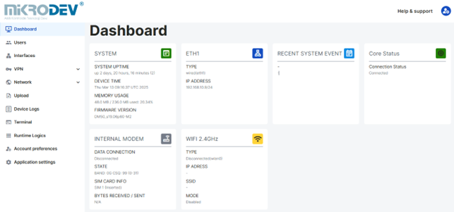
Control Panel Page: This page displays the real-time status of the device's system and network information.
Users Page: This page allows for the editing of users and the addition of new user definitions.
Interfaces Page: This page is where Ethernet, Wifi, and GSM Network settings are configured.
VPN Heading: Contains the OPENVPN page and the IPSEC page. OpenVPN and IPSec parameter settings for the device are made from these pages via the web server.
Network Heading: Contains Firewall, NAT, Bridge, and Port Forwarding pages. Security firewall, NAT, and Bridge settings, as well as port forwarding settings for the device, are configured from these pages via the web server.
Upload Manager Page: This page is used to upload firmware, projects, and SSL Certificates to the device. The Past tab allows tracking of past uploads.
Device Logs Page: This page is used to monitor the device's logs and view logs written to the SD Card. System logs and protocol logs viewed via the Web Server Interface can be downloaded in ".txt" format.
Terminal Page: This page is used to send AT commands to the device.
Real-Time Logics Page: This page allows monitoring and setting values of the project's block parameters loaded into the device. Output in CSV format can be obtained from this page.
Account Preferences Page: This page allows the user logged into the web server to edit their user information.
Application Settings Page: This page is used to adjust application theme and language options.
WEB SERVER LEFT SIDEBAR FEATURES
Hiding the Left Sidebar:
The left sidebar can be hidden by clicking on "Home" at the top of the page. The hidden left sidebar can be shown again by clicking on "Home".
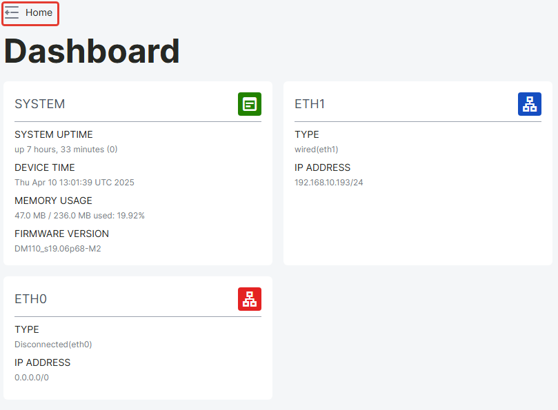
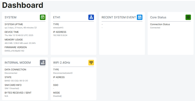
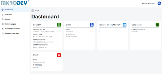
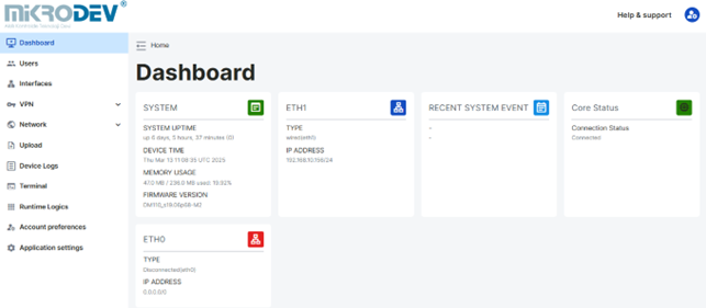
Control Panel Page
From this page, information such as device model, system uptime, system time, RAM usage, Firmware version information, Ethernet information, and recent system events can be accessed. When a connection is established through the Ethernet ports on the device, the status of ETH0 and ETH1 is updated as connected or disconnected.
All user types except guest and operator users defined via the Web Server Interface can access this page.
Users Page
Starting from Web Server 1.1.50, user management on the Users page can be performed in two different ways.
- Local User Management
Usernames, passwords, e-mail addresses, and access IPs can be defined.
Roles: Administrator, Operator, Technician, Guest.
- LDAP-based User Management
LDAP client settings can be configured in the LDAP Configuration section located under the Users tab.
When the LDAP method is selected, authentication and authorization are carried out through the LDAP directory server.
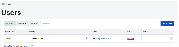
At the bottom of the user management page, there are three tabs: Active, Inactive, and LDAP. By clicking on these tabs, users can switch between the lists of locally defined active and inactive users, as well as the users authenticated through the LDAP server.
When a name is clicked, the text of the active tab becomes dark gray.
Only the Administrator user can access this page.
By clicking on the pencil icon to the right of the user names, personal information can be edited, and users can be set as active or inactive.
Users selected as active are listed in the active tab, while inactive users are listed in the other tab. To delete registered users, click on the eraser icon located here.
Adding a User
A new user can be added to the Web Server Interface from the add user tab.
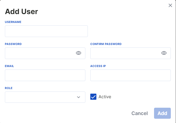
Username: A username is determined.
Password: The password must be a minimum of 6 and a maximum of 20 characters, and should include uppercase/lowercase letters, numbers, and symbols.
Mail: Should be in the format [email protected].
Access IP: This is the IP address of the computer that will access the Web Server Interface. (An access IP address must be defined for Operator, Guest, and Technician users. The Admin user can access the Web Server Interface from all IP addresses).
Different permissions for the created users are set from the permission options located at the bottom right of the page. There are 4 different user types. Each user type has different permissions on the Web Server interface.
- Operator: Can access the real-time logics page where the block values of the project loaded onto the device are located, the account preferences page, and the application settings page. Unlike the Guest user, the Operator user can monitor and set block values from the real-time logics page.
- Technician: Can access the control panel displaying the device's status, the interfaces page, the upload manager, the real-time logics page, the account preferences page, and the application settings page.
- Guest: Can access the real-time logics page where the block values of the project loaded onto the device are located, the account preferences page, and the application settings page. Unlike the Operator user, the Guest user can only monitor block values from the real-time logics page; they cannot set block values.
- Administrator: The Administrator is the most authorized person defined in the Web Server Interface. They can access all pages in the Web Server Interface.
Note: Multiple Administrator users can be defined in the Web Server Interface.
LDAP Configuration
Starting from Web Server 1.1.50, LDAP-based authentication is supported in the Users page. With this feature, user logins can be performed using accounts stored in an LDAP directory instead of local user accounts.
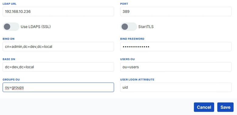
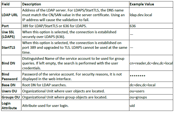
When the LDAP tab is selected in the Users page, the following parameters are displayed:
Role - Group Mapping
User roles in the Web Server are automatically assigned based on LDAP group memberships.

Certificate Requirements
If LDAPS (636) or StartTLS (389) is used, the CA or intermediate CA certificate of the LDAP server must be uploaded to the device.
The certificate upload is performed in the Upload Manager → LDAP Certificate Upload section.
The LDAP URL must use a DNS name; IP addresses cannot be used for certificate validation.
Test Connection
After the configuration is completed, the Test Connection button in the LDAP tab can be used to verify the connection.
The test output displays.
- Connection status (successful / failed)
- User bind result
- Groups the user belongs to
LDAP Login Flow
When logging in with LDAP credentials, the Web Server follows the steps below.
- The username and password are entered on the login page.
- The Web Server connects to the LDAP server to perform authentication.
- If authentication is successful, the user’s role is assigned based on group memberships.
- If authentication fails, an error message is displayed to the user.
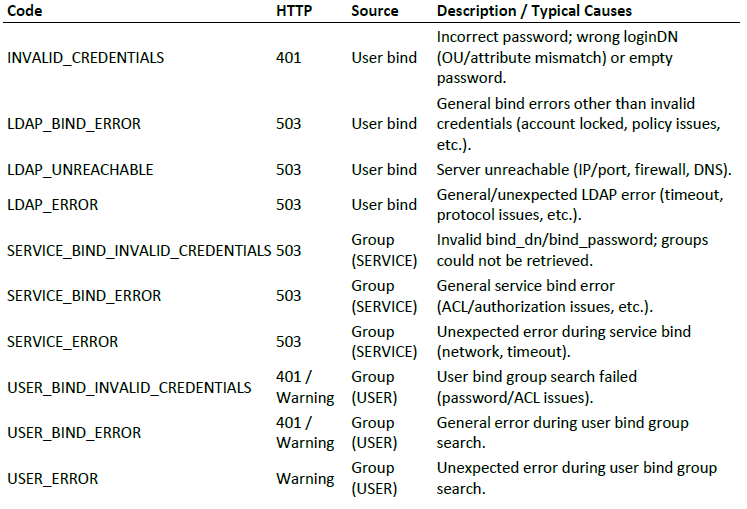
LDAP Troubleshooting
The following error codes may be displayed when problems occur during LDAP connection.
Interfaces Page
The Interfaces page contains a table where the device's network settings are configured. The Ethernet, GSM, and Wifi settings of the device can be edited from this table.
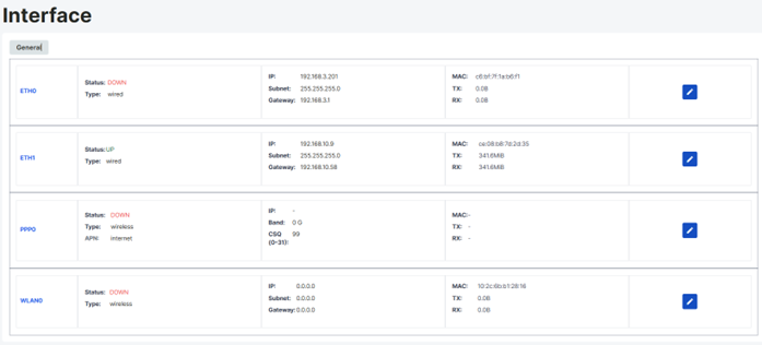
Ethernet Settings
The current Ethernet settings of the device can be monitored from the row labeled Eth0 and Eth1 in the table on the Interfaces page. The port connected via Ethernet can be seen from the status section, and Ethernet network configuration settings can be made by clicking the pen icon.
The Administrator and Technician users can access this page.
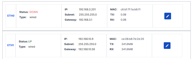
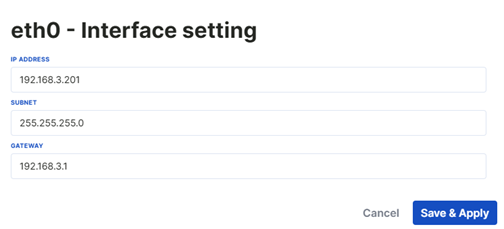
To configure the network for the desired Ethernet port, go to the corresponding row in the table. Access the Ethernet configuration settings page by clicking on the pen icon in this row. From the Ethernet network configuration page, enter the Ethernet IP address, Subnet Mask, and Gateway address, and click on "save & apply".
GSM APN Configuration
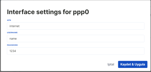
To connect to the device via GSM, the GSM settings to be connected to are configured from the ppp0 row of the interfaces table.
The Administrator and Technician users can access this page.

To configure GSM APN, click on the pen icon in the ppp0 row.
Enter the APN, Username, and Password information in the opened GSM APN configuration page and click on "save & apply".
Wifi Settings
Wifi configuration settings for the device via the Web Server Interface are made from the wlan row of the interfaces table.
The Administrator and Technician users can access this page.
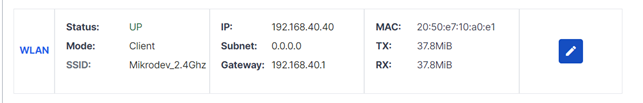
To configure the Wifi network, click on the pen icon in the WLAN row.
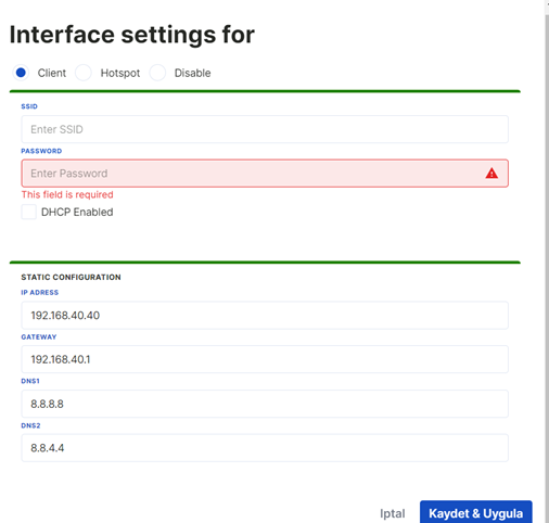
To connect to the device as a Client via Wifi, select the Client option from the options at the top of the page. Enter the SSID, Password, Static IP, Gateway address, DNS1, and DNS2 settings of the network to be connected to in the opened page and click on "save & apply".
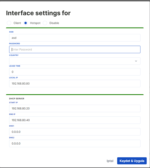
To connect to the device as a Hotspot via Wifi, select the Hotspot option from the options at the top of the page. Enter the SSID, Password, Country Selection, Lease Time, Local IP, DHCP Server Start IP, End IP, DNS1, and DNS2 settings for the HotSpot connection in the opened page and click on "Aply".
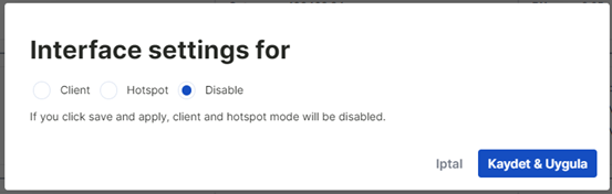
The Wifi feature of the device can be turned off via the Web Server Interface. Click on the pen icon in the WLAN row in the interfaces table. Select the "Disabled" option here. The Wifi feature of the device will be turned off.
VPN
OpenVPN Page
OpenVPN connection is made from the OpenVPN page under the VPN option in the left sidebar of the web interface. Certificates are uploaded to the device from the x509 tab of the opened page.
Only the Administrator user can access this page.
OpenVPN Auto Mode
OpenVPN Auto Mode is a mode that automatically starts the VPN when the system boots or the connection is lost, providing a continuous and secure connection.
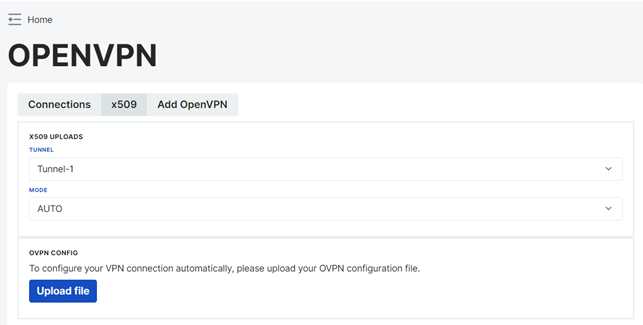
To establish a VPN connection in Automod mode, a configuration file with the .ovpn extension is required.
Note: The uploaded certificates and configuration procedures must be compatible with the same tunnel. For example, if a certificate is uploaded for Tunnel 1, the configuration steps for the same Tunnel 1 must be followed.
After the certificates are uploaded, the necessary fields are filled in from the Add Openvpn section. The fields to be filled in on this page vary depending on the mode selection.
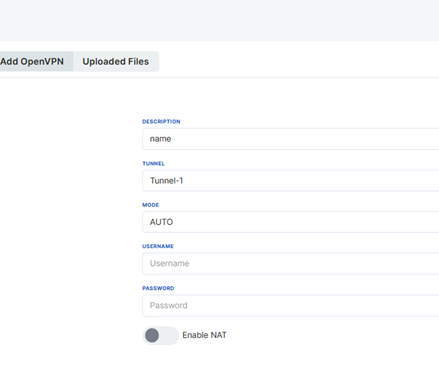
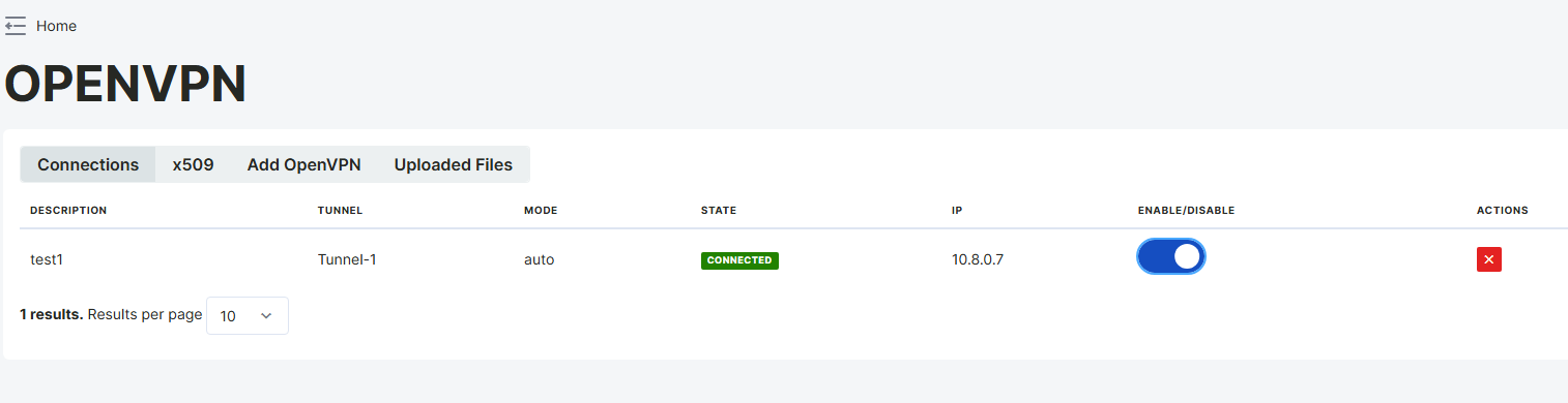
Added connections can be viewed in the "Connection" section, and these connections can be enabled or disabled. The created configuration file can also be downloaded. After enabling, the connection status and IP information will be updated. The ifconfig command can be used to verify if the connection is successful.
Client Mode
OpenVPN Client Mode allows the client to establish a secure and encrypted tunnel by connecting to the OpenVPN server. The client is assigned a private IP by the server, traffic is routed over the VPN, and the connection status can be monitored via ifconfig or the OpenVPN interface. Complete certificate and key files must be uploaded for secure communication.
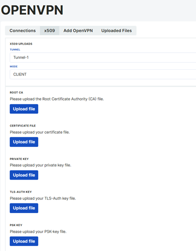
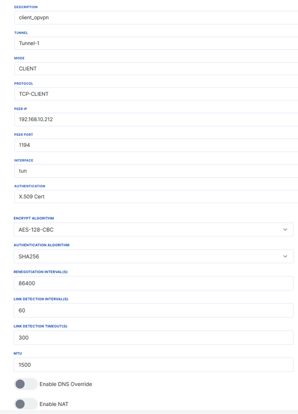
These files are necessary for the OpenVPN client to establish a secure connection. The uploaded certificates and keys can be viewed and managed from the Uploaded Files tab. By going to the Add OpenVPN tab, the server-related configurations are made in the tunnel where the certificates are uploaded. The settings here must match the server configurations. The following settings have been made according to the server's settings.
The same encryption and authentication algorithms set during server setup are entered here, and the add button is clicked. Save & Apply is selected, and the connection status and IP information are checked from the "Connection" section.
The same encryption and authentication algorithms set during server setup are entered here, and the add button is clicked. Save & Apply is selected, and the connection status and IP information are checked from the "Connection" section.
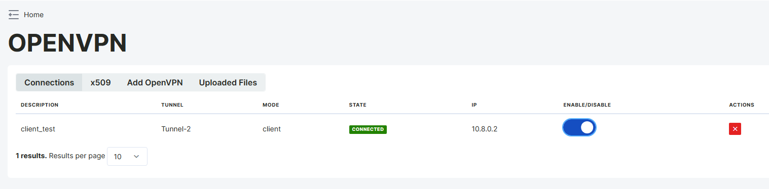
The example shows that the client_ovpn client has successfully connected via Tunnel-1. The client has been assigned the IP address 10.8.0.2, and the connection is active (Connected). The VPN connection can be turned on and off with the Enable option, and can be deleted with the red button on the right if necessary.
Server Mode
OpenVPN Server Mode is the mode that allows the VPN server to function as a central access point for clients. In this mode, the server manages client connections according to the determined protocols and security policies, and assigns IP addresses. Server Mode enables clients to communicate securely on the same network.
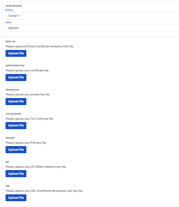
To run VPN in Server mode, server certificates must be generated on the machine where the VPN server is installed. The appropriate tunnel should be selected from the x509 tab and the certificate should be uploaded in server mode.
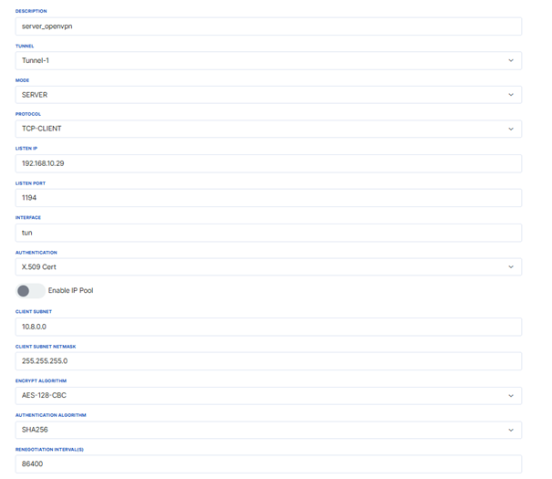
The same encryption and authentication algorithms set during server setup are entered here, and the add button is clicked. Save & Apply is selected, and the connection status and IP information are checked from the "Connection" section.
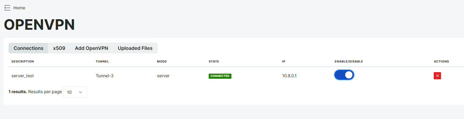
The example described here shows that OpenVPN Server Mode is active. The server is running with the IP address 10.8.0.1 and managing connections for clients. The connection status is seen as Connected, and the server is active.
IPsec Page
The IPSec page under the VPN options of the web server software is used to establish an IPSec tunnel between two devices that have received IP addresses via GSM.
Only the Administrator user can access this page.
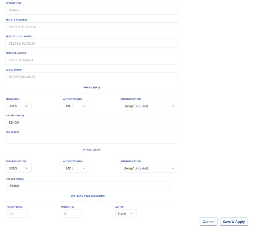
To add a new IPSec configuration, click on Add IPSEC. Select the Edit option. On the opened page, the public IP of the remote device should be written in the "Remote IP Address" section, while the local network of the remote device to be accessed should be written as the network ID and subnet in the "Remote Local Subnet" section.
The device's own public IP address should be written in the "Public IP Address" section, and the network ID and subnet of the local network to be accessed should be written in the "Local Subnet" section. A secret password is set in the PSK Secret section. The Time interval, timeout values, and Action sections should be filled in.
After configuring the phase1 and phase2 settings with the same values for both devices and clicking the "Apply" button, a tunnel will be established between the defined local networks.
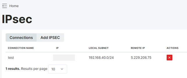
Active IPsec connections can be viewed in the "Connections" tab.
Network
Firewall Page
Firewall settings can be configured on the device via the web server to enhance network security. Access IPs and ports for the device can be determined by adding filter rules. Only the Administrator user can access this page.
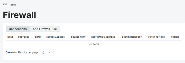
To add a new filter rule, click on "Add Firewall Rule". Continue with the "Add" option from the warning screen. Select the protocol type for which you want to add a connection filter to the device from the Protocol section. Enter the IP and port information you want to filter in the Source ip and port section, and enter the DM50 IP address in the destination ip section. From the Action section, select whether access to the device will be allowed or denied via the filtered IP or port information.
Fill in the necessary fields according to the filtering rule you want to create and click on "Apply" at the bottom of the page. There are three different modes for the firewall.
Input Mode
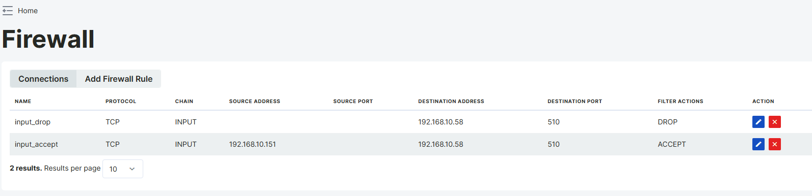
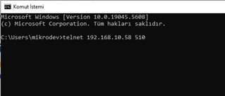
A firewall input rule is a security rule that controls traffic directly coming to the firewall itself. These rules determine whether requests from specific IP addresses, protocols, or ports will be accepted or rejected. In this example, access to port 510 of the 192.168.10.58 device is only allowed from the IP address 192.168.10.151, and connections from all other IP addresses are blocked.
To verify that the connection is working correctly, a connection should first be established from the IP address 192.168.10.151 to the port 510 of 192.168.10.58. This connection is expected to be successful. Then, the same connection should be attempted from a different IP address. In this case, the connection should fail. This example enhances security by ensuring that only authorized devices can access the specified port, while blocking all other access attempts.
In this configuration, a Modbus TCP/IP connection is established over port 510 of the device with IP address 192.168.10.151. By connecting to the 192.168.10.58 device via SSH, it has been verified with telnet that the 192.168.10.151:510 connection was successful.

Output Mode
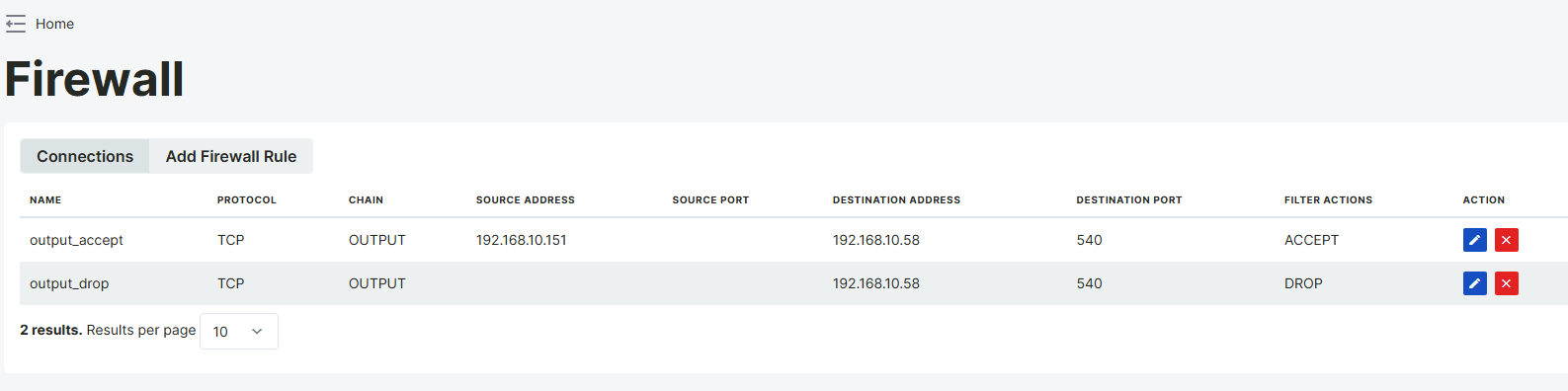
A firewall output rule is a security rule that controls traffic going out from the system. These rules are used to restrict or allow outgoing connections to specific IP addresses, protocols, or ports. In this example, security rules have been applied to traffic going from the IP address 192.168.10.151 to port 540 of 192.168.10.58. The ACCEPT rule allows outgoing traffic from 192.168.10.151, while the DROP rule blocks outgoing traffic from all other IPs to the same destination.
For the connection to be successful, a connection must be established from 192.168.10.151 to 192.168.10.58:540, and it should fail when attempted from a different IP. Additionally, port 540 of the target device must be open, and there should be no restrictions in the INPUT rules.
Forward Rule
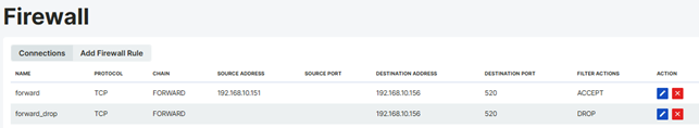
The Firewall Forward Chain is used to control traffic passing through a specific device. In the example described here, TCP traffic routed from the IP address 192.168.10.151 to the IP address 192.168.10.156 over port 520 is allowed, while traffic from all other sources is rejected.
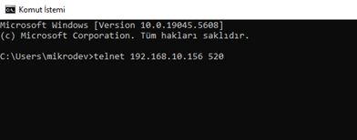
To verify the connection, a connection should be established from the IP address 192.168.10.151 to the IP address 192.168.10.156 with the command telnet 192.168.10.156 520. The connection is expected to be successful, while the connection should fail when the same operation is attempted from a different IP address.
This configuration enhances security by ensuring that only authorized devices can access the specified port.

NAT Page
NAT operation is performed from this page via the web server interface. NAT (Network Address Translation) is a method that allows multiple devices on the same network to access the internet using the same public IP.
Only the Administrator user can access this page.
For a new NAT configuration, the host gateway is first set as the router's IP. Then, click on "Add NAT Rule" from the NAT page. Continue with the "Add Rule" option from the information screen. Whether the WAN IP information is obtained statically or automatically is set via the action option. Select the SNAT option to set it statically or the Masquerade option to obtain it automatically. After selecting this setting, enter the host IP information in the Source Address section and the WAN IP information in the To Destination section. Enter the port information through which the host should access the WAN in the Port section.
Fill in the necessary fields according to the NAT configuration you want to create and click on "Save and Apply" at the bottom of the page. Once this process is complete, the host connected to the router will be accessible from the WAN via the specified port. Active NAT configurations can be viewed in the "Connections" tab.
SNAT
SNAT (Source NAT) is a NAT method that changes the source IP address of outgoing network traffic. It is generally used to allow devices on an internal network to access the internet through a specific external IP address. It is used to manage access from the internal network to the external network, enhance security, and hide network addresses.
For example, the internet traffic of a device with the IP address 192.168.1.10 can be routed through an external IP address such as 5.26.182.3 using SNAT to access the internet.
In the network configuration, communication was established using the gateway address 192.168.10.58 of the device. With the SNAT rule, traffic originating from the IP address 192.168.10.156 was routed to the address 81.6.111.229, and it was verified that the device successfully accessed the internet. This configuration allows a device that cannot directly access the internet to communicate by being routed through NAT.
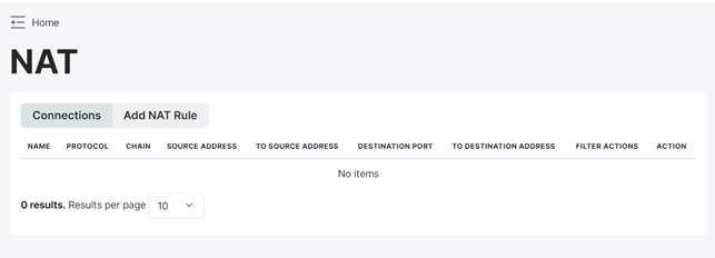
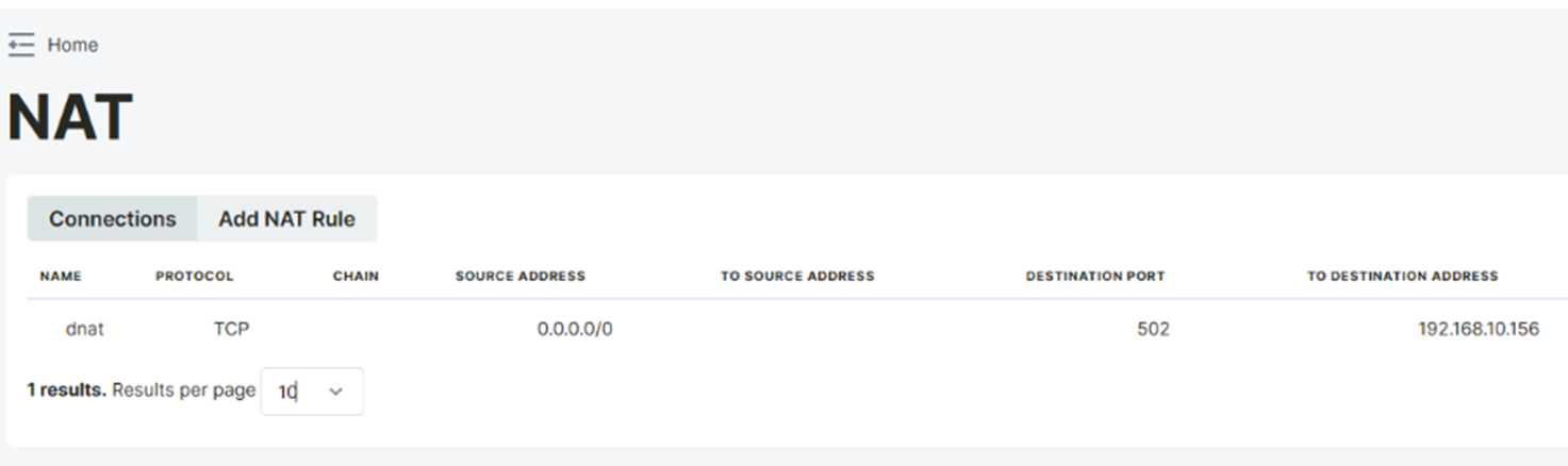
DNAT
DNAT (Destination NAT) is a NAT method that changes the destination IP address of incoming network traffic. It is generally used to route incoming requests from the external network to a specific server on the internal network. It is used for purposes such as port forwarding, providing external access to web and application servers, and load balancing.
For example, requests coming to the external IP on port 8080 can be routed to 192.168.1.10:80 on the internal network, allowing external clients to access the internal server.
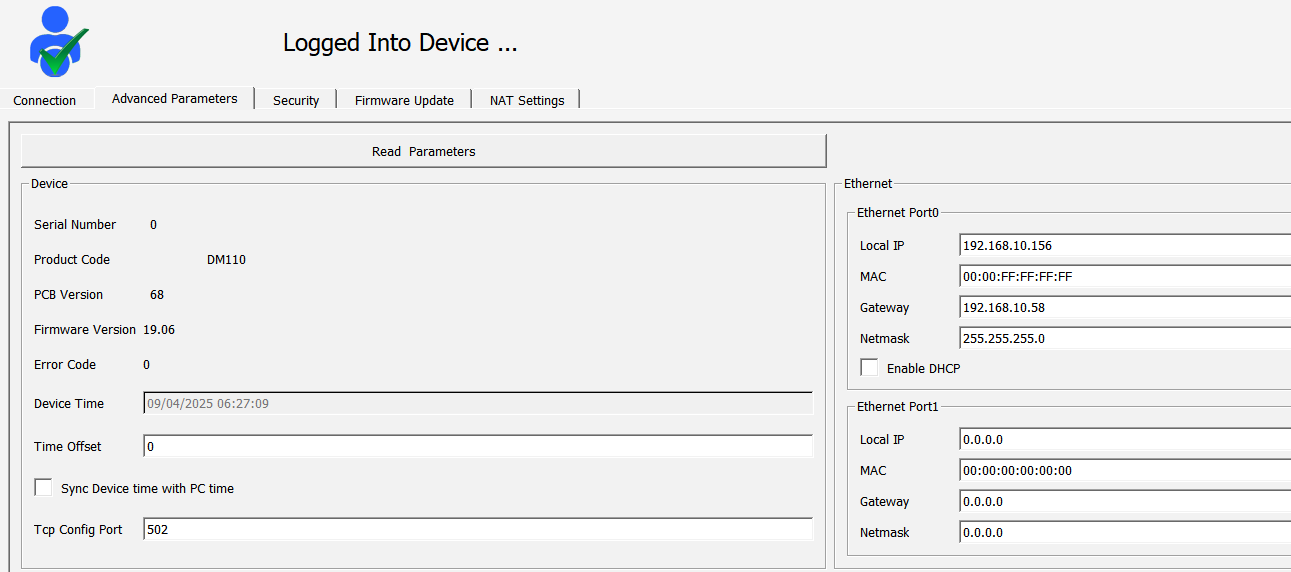
For the DM50 device to access the internet using a PPP connection, the Gateway address must be defined as 192.168.10.58. When a connection is established using port 502 via Telediagram, traffic should be routed to the DM110 (192.168.10.156) device with a DNAT rule. Thanks to this configuration, requests coming from the external network are routed to DM110 via DNAT, establishing a connection.
Bridge Page
The web server interface allows the router to create a bridge between its own interfaces. This feature allows connecting the networks to which IoT devices are connected and enables these devices to communicate. Only the Administrator user can access this page.
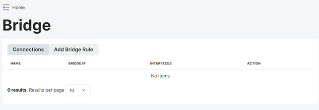
To add a new bridge rule, click on "Add Bridge Rule". Continue with the "Add Bridge" option in the information screen. Select the Ethernet connection you want to bridge and enter a new IP address in the Bridge IP address section. After making the necessary adjustments, click on "Save & Apply" at the bottom of the page.
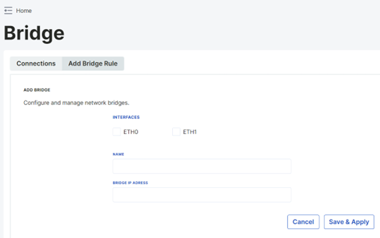
Active Bridge rules can be viewed in the "Connections" tab.
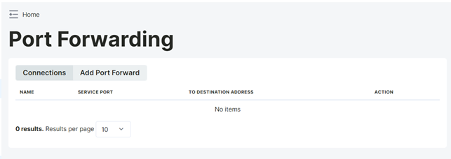
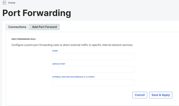
Port Forwarding Page
The web server allows port forwarding for devices connected to the router. This feature is achieved by redirecting requests arriving at a specific port number to a specific internal IP address and port. Only the Administrator user can access this page.
To add a new port forwarding configuration, click on "Add Port Forward". Continue with the "Add Rule" option in the information screen. Enter the port information to be forwarded in the server port section. In the Internal Destination Address section, enter the IP and port information of the device connected to the router.
After making the necessary adjustments, click on "Save & Apply" at the bottom of the page.
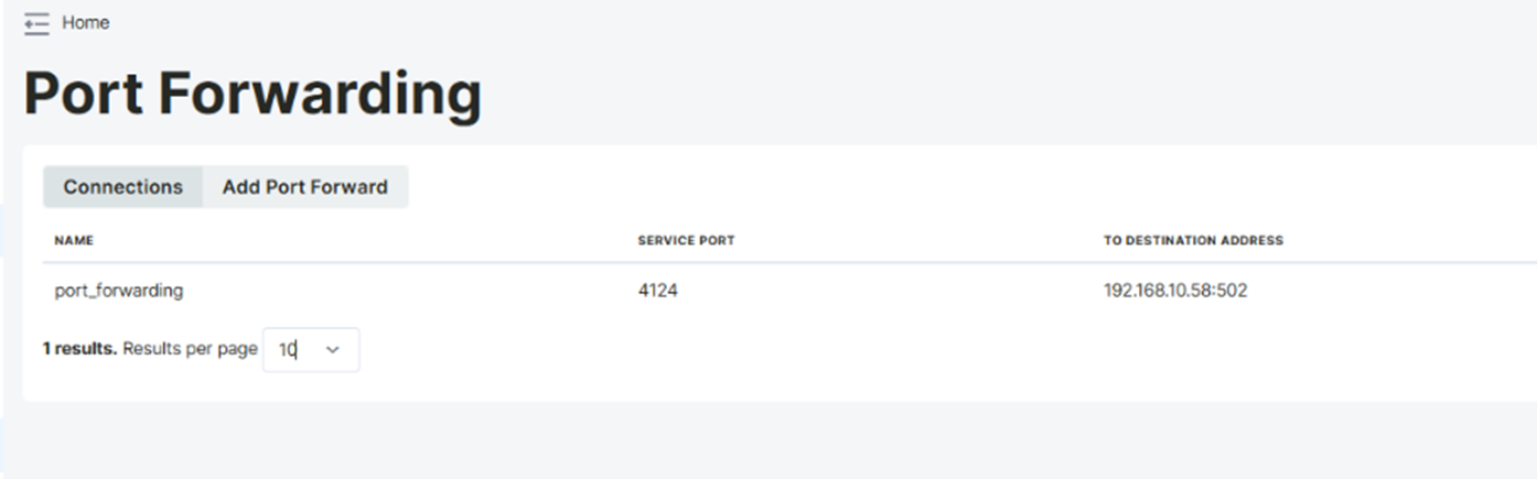
Active port forwarding configurations can be viewed in the "Connections" tab.
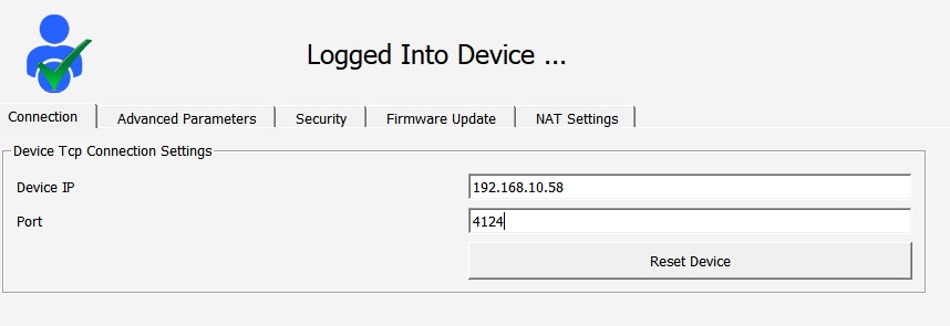
In the example described here, external network traffic arriving at port 4124 is redirected to port 502 of the device with the IP address 192.168.10.58. While connections coming from the external network are routed using port 4124, the 192.168.10.58 device on the internal network is made ready for connection via port 502. This configuration allows requests from the external network to be redirected to a specific device on the internal network.
Upload Manager Page
Firmware, project, and SSL certificate uploads to the DM50 device from the Web Server interface can be performed on this page without using the Telediagram program. The date and time of the last file uploads performed via the Web Server interface are shown in the History tab.
Starting from Web Server 1.1.50, the Upload Manager also includes an LDAP certificate upload feature. With this feature, the device can establish a secure TLS connection by uploading the CA/intermediate CA certificates of the LDAP server.
The Upload Manager page can be accessed by Administrator and Technician users.
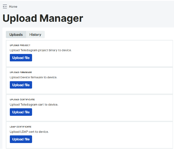
From the project upload section, the project file prepared via Telediagram is uploaded to the device. The extension of the file to be uploaded must be ".bin".
Firmware updates for the device are performed from the firmware upload section. The core file to be uploaded is accepted.
Updates of SSL certificates are made from the update SSL certificate section. The extension of the files to be uploaded must be ".crt, .pem".
LDAP Certificate Upload (new in 1.1.50): LDAP server CA or intermediate CA certificates can be uploaded here. These certificates allow the device to establish a secure LDAP connection over TLS. The file extensions must be “.crt” or “.pem”.
To upload a file to the device, click select file under the file type to be uploaded and select the relevant file. After selecting the appropriate file, click on the upload option on the right side.
Device Logs Page
Log record information belonging to the device can be accessed from this page. The device logs page consists of 4 tabs: the settings tab where protocol log settings are made, system logs, protocol logs, and SD card logs. Switching between tabs is done by clicking on the settings, system logs, protocol logs, and SD card logs texts at the top of the page. The text of the selected tab becomes dark gray.
Only the Administrator user can access the device logs page.
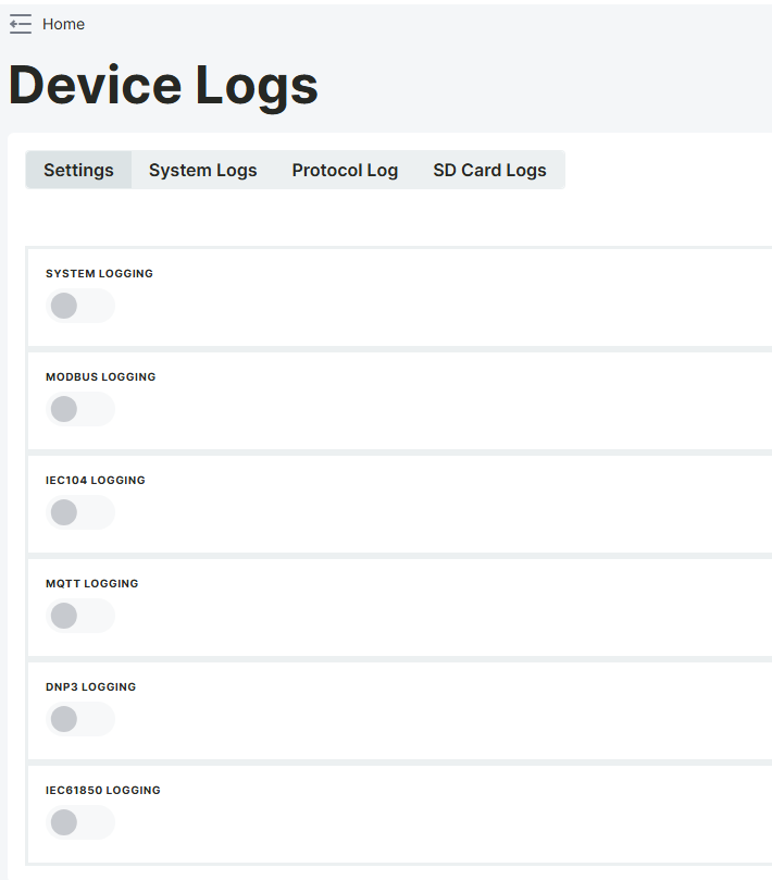
Settings Tab
From the device log settings tab, IEC104, MQTT, DNP3, and IEC61850 protocol logs of the project loaded into the device can be turned on and off.
To turn on protocol logs, the slider button next to the protocols should be selected. After the selection is made, the icon here will turn blue.
Protocol logs for which logging is turned on here are displayed in the protocol logs tab.
Note: Protocols for which protocol logs are not turned on will not appear in the protocol log tab filter.
Note: To monitor protocol logs in the protocol log tab, the monitoring and modification option must be checked in the block's special settings of the blocks in the Telediagram project.
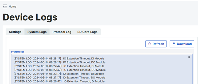
System Logs Tab
System logs belonging to the device are monitored from this tab. The system logs displayed on the screen can be exported in ".txt" format with the export option.
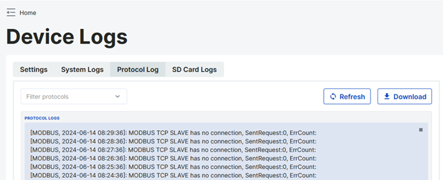
Protocol Logs Tab
Protocol logs of the project located within the device are monitored from the protocol logs tab. To monitor on this page, the protocol logs to be displayed must be turned on in the Settings tab under heading 4.7.1.
The protocol logs displayed on the page can be filtered. For this, the filtering option located in the upper right corner is used.
When All is selected, all protocol logs for which logging is turned on will be displayed on the screen.
When IEC104 is selected, only logs related to the IEC104 protocol will be displayed on the screen.
When MQTT is selected, only logs related to the MQTT protocol will be displayed on the screen.
When DNP3 is selected, only logs related to the DNP3 protocol will be displayed on the screen.
When IEC61850 is selected, only logs related to the IEC61850 protocol will be displayed on the screen.
When the Refresh button is clicked, the protocol logs page filtered by the selection is refreshed.
The displayed logs can be exported in ".txt" format with the export option.
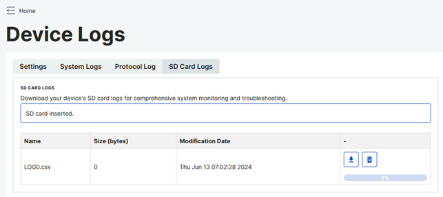
SD Card Logs Tab
From the SD Card Logs tab, as long as an SD card is inserted in the device, the log file created in it can be accessed via the web server. From this tab, the log file can only be downloaded and deleted in CSV format. The last updated date and size of the file can also be seen.
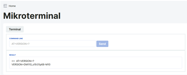
Terminal Page
AT commands can be sent to the device via the terminal page. You can access the list of AT commands that can be sent to the device from here.
Only the Administrator user can access this page.
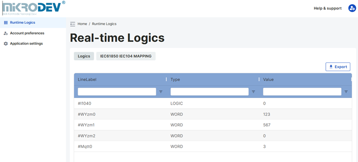
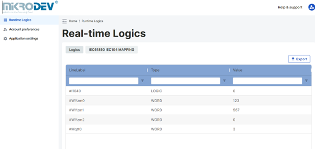
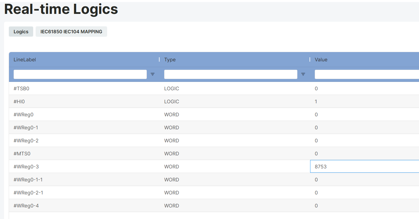
Real-Time Logics Page
The block parameter values of the project loaded onto the device can be read and values can be assigned from the real-time logics page.
All users defined in the Web Server Interface can access this page
The number of tag labels to be displayed on the page can be selected from the page size section at the bottom right of the page.
The displayed block parameters can be exported in CSV format with the export option located at the top right corner of the page.
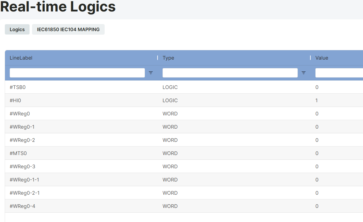
Tag Label: This is the section where the block tag label is located.
Type: This is the section where the data type of the relevant block is written.
Value: This is the section where the block value of the relevant block is written.
Value assignments are made from the value section located to the right of the relevant block tag label. When the value section of the relevant block tag label to be assigned a value is double-clicked, the value entry window becomes active. A value is entered here, and the ENTER key is pressed.
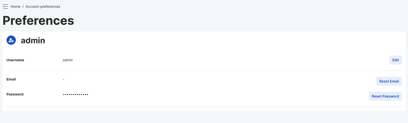
Account Preferences Page
This is a page that all users logged into the web server can access and edit their user information. On this page, users can update their personal information, change their passwords, and manage other account settings. This allows each user to easily manage and keep their account information up to date.
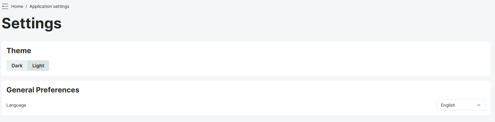
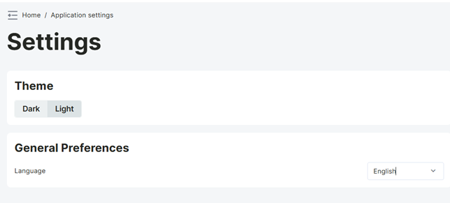
Application Settings Page
It offers users the ability to manage various personalization and application preferences. From this page, you can select the application theme and change the application language. This page allows users to customize the web interface according to their own needs and preferences, providing a more user-friendly experience.
All users defined in the Web Server Interface can access this page.
LOGGING INTO THE DM50 WEB SERVER INTERFACE AS OPERATOR, TECHNICIAN, AND GUEST USER
Logging in as Operator
To log in as an operator, an administrator user must first create a user with the operator type from the users page.
The admin assigns a different Access IP to each operator user they create.
Operators can only access the DM50 web server interface from the IPs defined for them. If an operator user tries to log in to the web server with a computer IP different from the Access IP defined for them, they will receive an "IP's access is denied!" warning and will not be able to log in to the web server.
Note: To log in to the DM50 web server interface as an operator user, the computer's IP must first be set to the Access IP defined by the admin. Otherwise, access to the DM50 web server interface will not be possible.
Logging in as Technician
To log in as a technician, an administrator user must first create a user with the technician type from the users page.
The admin assigns a different Access IP to each technician user they create.
Technicians can only access the DM50 web server interface from the IPs defined for them. If a technician user tries to log in to the web server with a computer IP different from the Access IP defined for them, they will receive an "IP's access is denied!" warning and will not be able to log in to the web server.
Note: To log in to the DM50 web server interface as a technician user, the computer's IP must first be set to the Access IP defined by the admin. Otherwise, access to the DM50 web server interface will not be possible.
Logging in as Guest
To log in as a guest, an administrator user must first create a user with the guest type from the users page.
The admin assigns a different Access IP to each guest user they create.
Guests can only access the DM50 web server interface from the IPs defined for them. If a guest user tries to log in to the web server with a computer IP different from the Access IP defined for them, they will receive an "IP's access is denied!" warning and will not be able to log in to the web server.
Note: To log in to the DM50 web server interface as a guest user, the computer's IP must first be set to the Access IP defined by the admin. Otherwise, access to the DM50 web server interface will not be possible.
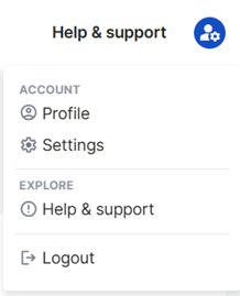
LOGGING OUT OF THE DM50 WEB SERVER INTERFACE
You can securely log out of the web server interface by clicking on the user icon in the upper right corner and selecting the Logout option from the menu that opens.