DNP3 Application Notes
DNP3 Slave
General Information
DNP3 protocol is a distributed communication protocol. Primary advantage are:
• Time-labeled variable support
• Ability to re-send the events that occurred during the absence of communication when connected with the time tags.
• The ability of SCADA to automatically send changes without the need to query.
• Ability to query multiple variables as a class, not individually
• Time syncronization
DNP3 Slave Driver
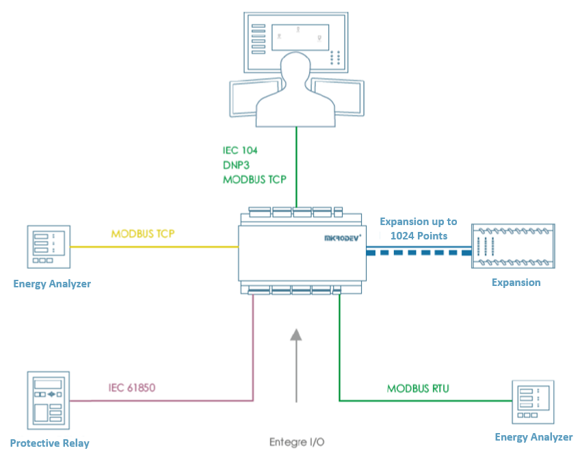
Mikrodev RTU devices are supports DNP3 SLAVE mode and gives service to DNP3 supported systems over TCP IP and/or Serial Port . The following services are supported:
1- Bulk object reading with Class object query
2- Adding Object Static Variation and Object Event Variation (based on the object types of the specified variables)
3- Time syncronization
4- Event control in instantaneous measurement data as a percentage and level
5- Automatic send the event datas
6- Periodically send the points of data
DNP3 Slave Block Definitions
Connections
Connections Explanation
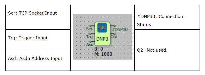
Ser: TCP Socket Input
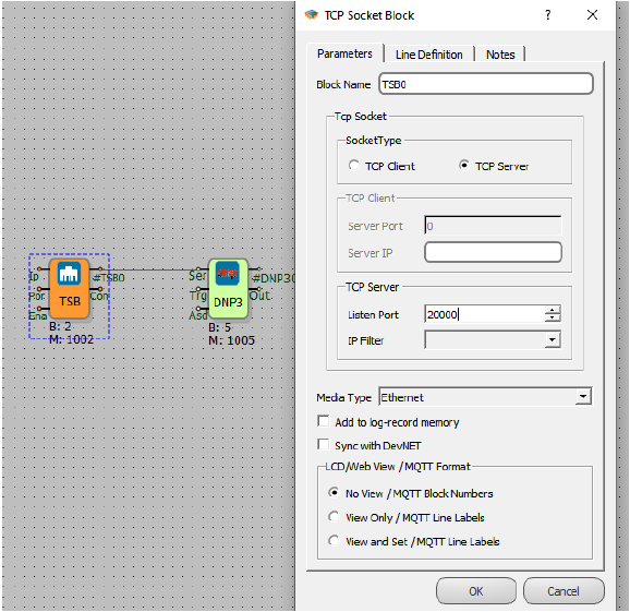
The TCP server socket block, where the DNP3 protocol will run, is connected from this input.
Trg: Trigger Input
The trigger input for periodically send operation. Works as a rising edge.
Asd: Asdu Address Input
It is used as an ASDU address entry.
#DNP30: Connection Status
It is used to control the connection status between the master and the slave. DNP3 gives the value 1 when the connection with the master is established.
Block Special Settings
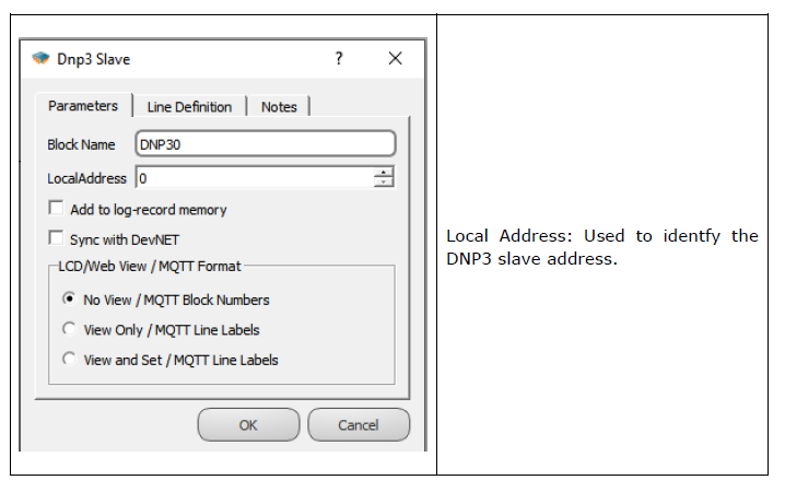
Adding a DNP3 Slave block to the project activates the DNP3 protocol on the RTU.
Serial Input: A TCP or Serial Port block is added to the serial input of the DNP3 block.
Note: To serve multiple servers, a DNP3 Slave block must be added to the telecontrol project for each server.
Trg Input: On the rising edge of the trigger, selected objects with active periodic transmission among the DNP3 objects are sent to the server with a Periodic Cause of Transmission (COT). This input can be left empty if periodic transmission is not required.
Asd Input: If the DNP3 ASDU address needs to be configured externally instead of through block-specific settings, the Asd input is used.
#DNP30 Output: It is used to control the connection status between the master and the slave. DNP3 gives the value 1 when the connection with the master is established.
When a DNP3 Slave block is added to the RTU logic project, the DNP3 protocol becomes active on the RTU. The association of this protocol with the variables in the RTU is achieved through the variable address table. Variables defined in this table ensure proper communication with the master device.
Object 60 and Object 80 are critical elements of the DNP3 protocol and must be defined in the variable address table to enable communication with the master device:
• Object 60: Enables the classification and retrieval of event and static data. This object allows the master device to send queries targeting specific classes (Class 0, Class 1, Class 2, Class 3) and retrieve only the relevant data.
• Object 80: Serves to monitor the internal status and diagnostic information of the device. This object ensures control of diagnostic details such as the RTU’s health status and communication state.
To define Object 60 and Object 80 variables, navigate to the variable address table. Inputs such as tag names and starting addresses can be chosen arbitrarily.
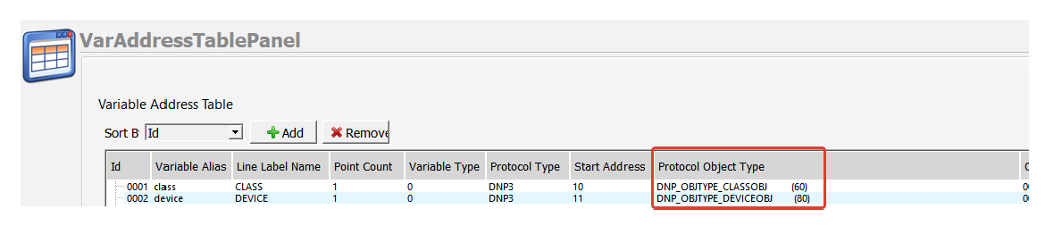
Note: If the DeviceObj (Object 60) and ClassObj (Object 80) variables are not defined in the variable address table, communication between the DNP3 Master and Slave cannot be established.
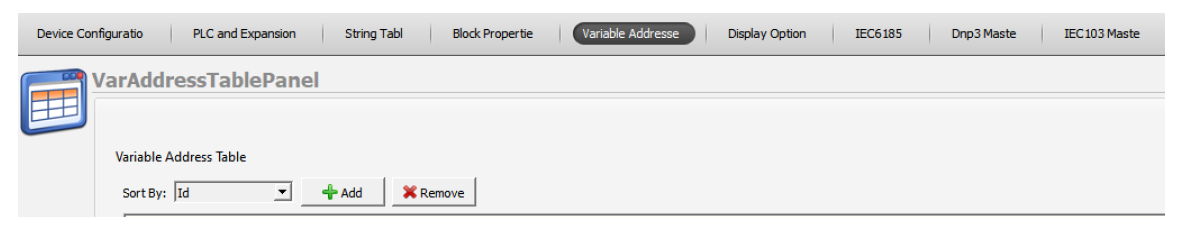
DNP3 Variable Table Definitions
Variable Table
To RTU logic project, DNP3 becomes active in the DNP3 protocol within the RTU with the addition of the Slave Block to DNP3. Variables that in the RTU logic, The association of DNP3 is provided in the variable address table.
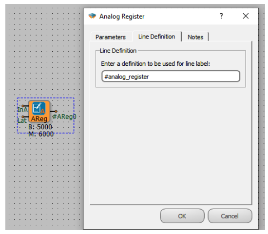
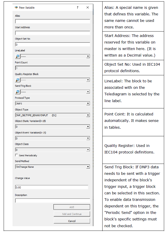
Line Label Definition
A line tag can be defined for all blocks added to the telecontrol project. To associate protocol addresses in the variable address table, the relevant blocks must have a defined line tag.
Line Label Attribution
Associating the protocol adresses with line labelss, The variable is provided from the menu by pressing the “Add” button in the address table.
DNP3 Object Class
The class structure in the DNP3 protocol enhances communication efficiency by grouping data based on priority and categories. Data is organized into four main classes: Class 0, Class 1, Class 2, and Class 3. These classes are defined according to the object classes specified in the variable address table.
Class 0: This class is reserved for static (unchanging) data. Static data reflects the current value of a variable in a device. For example, information like the current measurement value of a sensor or the current position of a switch falls under Class 0. Class 0 data is typically low-priority and is sent only when requested by the master. Points assigned to Class 0 do not report events. Reading all static data types in a device is equivalent to reading Class 0.
Class 1: This class is used for high-priority event data. An event is triggered by a change in a data point or another trigger condition. Class 1 events are considered more urgent compared to other classes. Typically, high-priority information such as significant state changes or critical alarms is assigned to this class. For instance, an intrusion detection event in a security system could be reported as Class 1.
Class 2: This class is used for medium-priority event data. Class 2 events are less urgent than Class 1 events but have higher priority than Class 3 events. Moderately critical state changes or events are assigned to this class. For example, a warning signal from a device could be reported as Class 2.
Class 3: This class is used for low-priority event data. Class 3 events have the lowest priority among the classes. Routine events or less critical state changes are typically assigned to this class. For example, a device measurement exceeding a predefined range might be reported as Class 3.
Note: If you want to receive DNP3 data from the master device with the Unsolicited Enable query, the relevant address must have a class definition other than 0. Unsolicited messages cannot be sent to addresses with a class definition of 0. Therefore, the class structures of the variables must be carefully defined to ensure correct transmission of critical or event-based data.
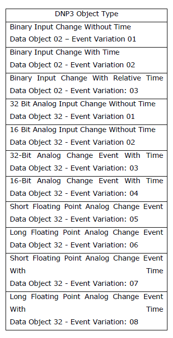
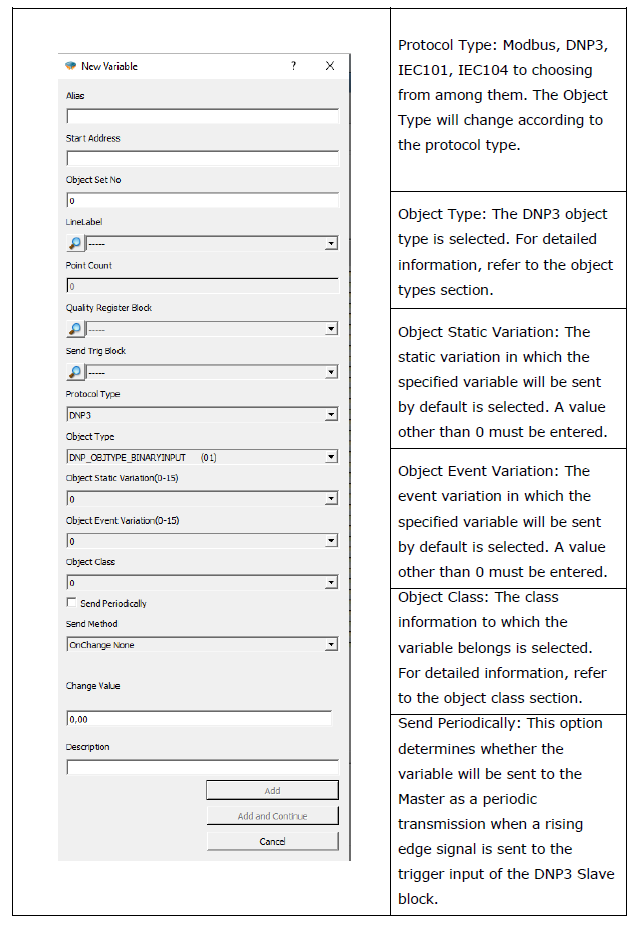
DNP3 Object Types
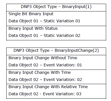
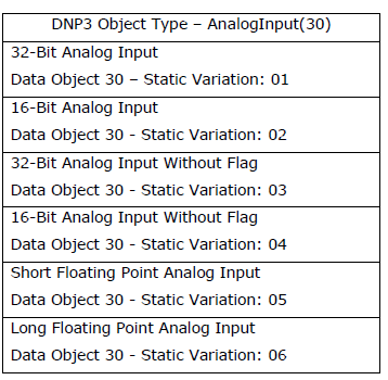
The DNP3 slave device responds to variation 0 commands for the object types listed below using the static and event variations defined in the variable address table. These objects are used to query and transmit change events or static states.
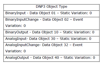
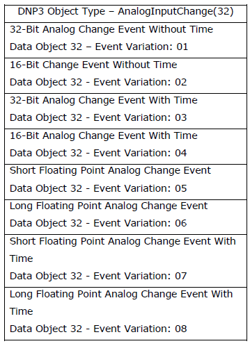
Note: The Binary Input Change and Analog Input Change object types are not defined in the variable address table. Instead, the Binary Input and Analog Input object types are used for change tracking. If the "send on change" feature is enabled for these objects, when a change occurs in these variables, the DNP3 Slave device responds to the Master device's query accordingly (Binary Input Change or Analog Input Change).
DNP3 Object Types in Reading Direction
According to the DNP3 protocol, when the master sends a Variation 0 query to the slave device, the slave device responds only with the static variations defined in the variable address table. In addition, when the master sends a query for a variable, for example, with variation 1, the slave device responds with variation 1, regardless of whether the relevant variable is defined with a different variation.
Supported Variations of Binary Input Variables
Supported Variations of Binary Output Variables

Supported Variations of Analog Input Variables
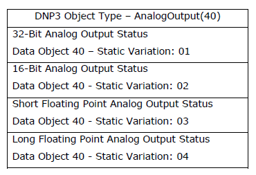
Supported Variations of Analog Output Variables
Note: No variations other than those supported by the variables should be defined. The slave device only supports the variations specified here. Therefore, using different variations may lead to communication errors.
Note: Variation 0 is used by the master device to query the variations defined by default on the slave device. Therefore, variation 0 should not be defined on the slave device.
DNP3 Object Types in Control Direction
The object types supported in the control direction on the slave device are as follows:

There are 2 different control object types defined in the variable address table in the device. These are Control Relay (12) and Control Analog (41) object types.
DNP3 Event Mechanism
Event Definition for DNP3 Objects
The Binary Input Change and Analog Input Change object types are not defined in the variable address table. Instead, Binary Input and Analog Input object types are used for change tracking. If the "send on change" feature is enabled for these objects, the DNP3 Slave device responds to the Master device's query appropriately when a change occurs in these variables. This process occurs only when the change is recorded as an event within the corresponding data class, ensuring that only current or updated data is prioritized in communication.
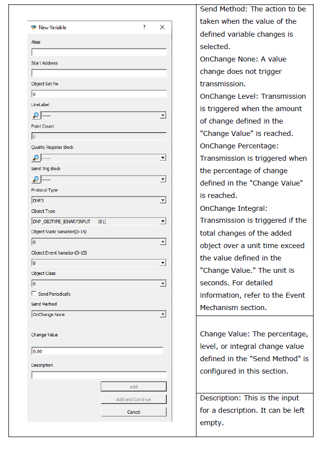
In the variable address table, the "send on change" option is available for DNP3 objects. The action to be performed when the value of the defined variable changes is selected through this menu: OnChange None: Value changes do not trigger a transmission.
OnChange Level: Transmission is triggered when the change reaches the amount defined in the "Change Value."
OnChange Percentage: Transmission is triggered when the change reaches the percentage defined in the "Change Value."
OnChange Integral: Transmission is triggered when the total of the changes within a unit time exceeds the value defined in the "Change Value."
The Change Value setting, together with the Send Method, configures the percentage, level, or integral change value.
Example; If the transmission method for a DNP3 object defined in the variable address table is set to "integral change" and the change amount is set to 10, the following behavior occurs:
If the change amount is 2, the transmission will occur after 5 seconds, calculated as 10/2(change value divided by the change amount).
If the change amount is 5, the transmission will occur after 2 seconds, calculated as 10/5. If the change amount is 15, the transmission will trigger immediately since it exceeds the defined change value.
This mechanism ensures efficient communication by sending only the necessary data based on the configured conditions.
Instant Transmission of DNP3 Event Statuses
The DNP3 Slave device labels the conditions defined as "Send on Change" and the changes detected as events. When a tagged event occurs:
If the connection between the slave and the master exists and the master is enabled to accept unsolicited messages, the corresponding object is immediately transmitted as an unsolicited message.
Note: Unsolicited sending is only performed if the master supports this feature and is set to active.
Note: If you want to receive DNP3 data from the master device with the Unsolicited Enable query, the relevant address must have a class definition other than 0. Unsolicited messages cannot be sent for addresses with a class definition of 0.
Event Statuses When There is No Connection with DNP3 Master
The RTU device labels the situations defined as send in change and the situations where change is detected as events. This data is stored in the device as Class data. This class event data stored in the memory can be read by the Master device with Class 1, Class 2 or Class 3 data read queries. If unsolisted sending is enabled, the RTU device automatically transmits this data to the master. If there is no connection between the slave and the master, the RTU device adds the class data to the event record memory and stores it to be sent when the connection is reestablished.
Note: For the storage process, the Add to log-recording memory option must be selected from the special settings of the DNP3 Slave block.
Note: If you want to send all class data stored in the log-recording memory to the master when the connection is established, the Synchronize with DevNET option must be selected from the special settings of the DNP3 Slave block.
Note: The values of objects that are selected as active for periodic sending between DNP3 objects are not perceived as events. In other words, periodic sendings are not added to the log-recording memory when there is no connection.
Events in DNP3 variables are transmitted via the DNP3 object types specified in the table below: