IEC61850 Version 2 Application Notes
IEC61850 Protocol
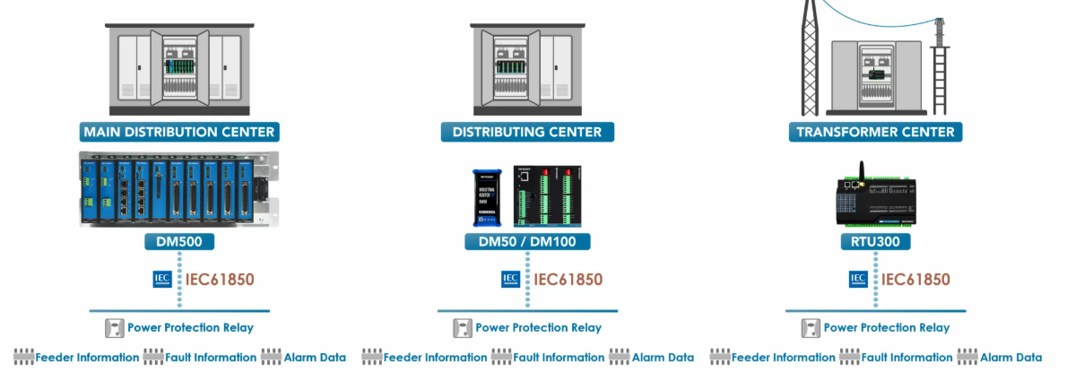
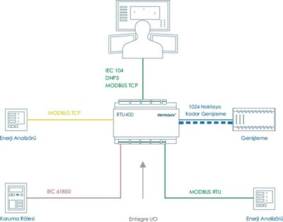
IEC 61850 is a communication protocol used especially in electrical distribution systems. It was developed to standardize and facilitate data exchange between components in the electrical power infrastructure. This standard ensures that components such as transformers, circuit breakers, protection relays, and other power grid elements can communicate securely and quickly with each other.
Mikrodev supports the IEC 61850 protocol in many of its RTU (Remote Terminal Unit) products. The necessary configuration can be easily done thanks to the IEC 61850 Browser tool in the Telediagram programming editor. The Mikrodev RTU device operates as a Client and uses files with the ".scl" extension to configure IEDs (Intelligent Electronic Devices).
There are three different data reading methods via the IEC 61850 Browser:
- Data Object Reading
- Dataset Reading
- Report Reading
These options determine which data will be retrieved and how, and ensure their association with the relevant blocks in the editor**. The settings made are exported and must be imported into the IEC 61850 Table Panel located in the Telediagram programming editor. Communication is completed by defining the IP address, port information, and connection commands of the IEDs via this panel.
Note: This document covers DM series Mikrodev devices with version 19 and above. For DM and RTU series devices with versions prior to 19, please refer to the IEC 61850 Application Note Version 1.0 document.
DATA OBJECT
Data Object Read
To create a new project using MDV61850 Browser, follow the steps below:
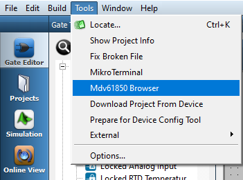
To open MDV61850 Browser, navigate to the Tools menu in the Telediagram program and click on the MDV61850 Browser option.
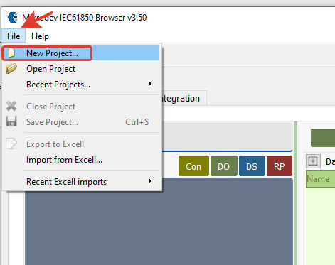
After opening MDV61850 Browser, click on the New Project option from the File menu.
In the opened window, select the IEC 61850 configuration file (.cid, .icd, .scl) retrieved from the relay.
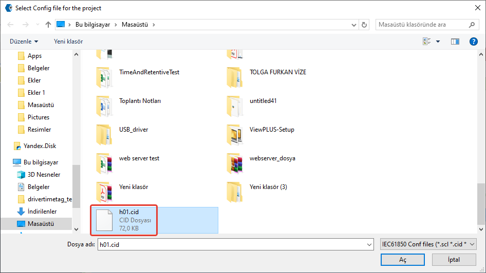
A project name is specified, and the file path where it will be saved is selected. A new project is created by clicking the Create Project button.
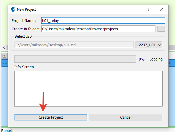
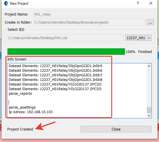
When a new project is successfully created, the Info screen displays information about the 61850 configuration file retrieved from the relay. If the message "Project created" appears on the screen, it means the process has been successfully completed.
Note: For detailed information about MDV61850 Browser, please refer to the MDV61850 Browser Application Note document.
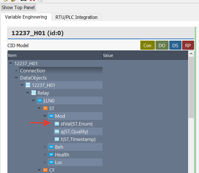
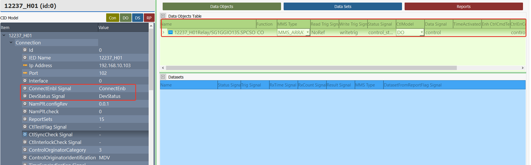
In MDV61850 Browser, the data objects to be read can be selected by double-clicking on them from the Data Objects List on the right. The selected data objects are then displayed in the Data Object Table.
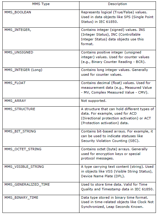
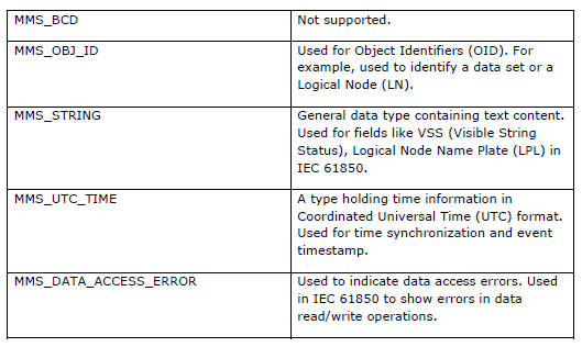
In the MMS_Type column, the variable type of the selected data is automatically updated. Based on the specified data type, a telediagram block should be assigned accordingly.
In the Connection section of MDV61850 Browser, the following telediagram blocks must be assigned to open/close the connection between the relay and RTU and to monitor the connection status:
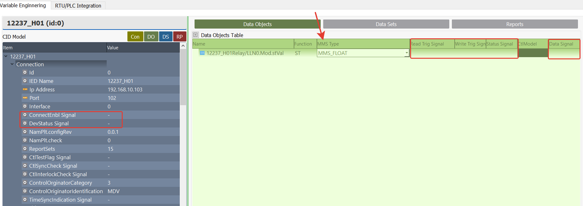
ConnectEnb Signal: This signal is used to control the connection between the relay and the RTU. A block to be associated from Telediagram is selected.
When a trigger signal (value 1) is applied to this label in Telediagram, the RTU connects to the relay and communication is initiated.
To disconnect, this signal must be set to 0.DevStatus Signal: This is a signal indicating the connection status and must be assigned with an appropriate block to be associated from Telediagram.
The possible values and their descriptions for this signal are as follows:
0 CLOSED Connection is closed.
1 CONNECTING Connecting.
2 CONNECTED Connected.
3 CLOSING Connection is being closed.
15 NAMEPLATE_SEND Nameplate information is being sent.
16 NAMEPLATE_WAIT Waiting for nameplate information.
17 NAMEPLATE_FAILED Nameplate information could not be retrieved (error occurred).
Note: When the CONNECTED (2) value is received, the connection between the RTU and the relay has been successfully established.
When CLOSED (0) or CLOSING (3) values are received, it indicates that the connection is closed or in the process of closing.
The values related to NAMEPLATE (15-17) are used during the connection process while retrieving device information from the relay.
Read Trig Signal: The trigger block to be associated in Telediagram to read the data object is selected.
Write Trig Signal: The trigger block to be associated in Telediagram to send a command to the data object is selected.
Status Signal: Used to track the status of read or write operations. The block to be associated from Telediagram is selected.
The possible values and their descriptions for this signal are as follows:
0: WAITING/FAIL, Request response is awaited or the operation failed
1: OK, The request was completed successfully.
2: MISMATCH, Operation failed due to incompatibility.
3: TIMEOUT, Operation failed due to timeout.
4: FAILED, Operation failed due to internal error.
100 and above: Operation failed due to library error. (Error code: can be calculated as status value + 100).
Note: When the Status Signal value is "1" (OK), the read or write operation has been completed successfully. When the value is "0" (WAITING/FAIL), the operation has failed or a response is being awaited.
Note: When the Status Signal is 100 or above, the value written in CtrlErrCode Signal should be checked for the error code.
The Library Errors and their descriptions written in CtrlErrCode are as follows.The value read should be the error code written here + 100. For example, the value to read for the IED_ERROR_NOT_CONNECTED code is 100+1 = 101.
* 0  IED_ERROR_OK: No error, service request completed successfully.
* 1  IED_ERROR_NOT_CONNECTED: Client is not connected, service request cannot be performed.
* 2  IED_ERROR_ALREADY_CONNECTED: Connection request failed because the client is already connected.
* 3  IED_ERROR_CONNECTION_LOST: Connection lost, service request cannot be performed.
* 4  IED_ERROR_SERVICE_NOT_SUPPORTED: Service or parameter not supported by client or server is being used.
* 5  IED_ERROR_CONNECTION_REJECTED: Server rejected the connection request.
* 6  IED_ERROR_OUTSTANDING_CALL_LIMIT_REACHED: Maximum concurrent call limit exceeded, new request cannot be sent.
* 10  IED_ERROR_USER_PROVIDED_INVALID_ARGUMENT: API function called with an invalid argument provided by the user.
* 11  IED_ERROR_ENABLE_REPORT_FAILED_DATASET_MISMATCH: Report activation failed, dataset mismatch.
* 12  IED_ERROR_OBJECT_REFERENCE_INVALID: Object reference is invalid.
* 13  IED_ERROR_UNEXPECTED_VALUE_RECEIVED: Unexpected type of object received.
* 20  IED_ERROR_TIMEOUT: Communication with the server failed, timeout occurred.
* 21  IED_ERROR_ACCESS_DENIED: Server denied access to the object or service.
* 22  IED_ERROR_OBJECT_DOES_NOT_EXIST: Server reported that the requested object does not exist.
* 23  IED_ERROR_OBJECT_EXISTS: Server reported that the requested object already exists.
* 24  IED_ERROR_OBJECT_ACCESS_UNSUPPORTED: Server does not support the requested access method.
* 25  IED_ERROR_TYPE_INCONSISTENT: Server reported that the requested object is not of the expected type.
* 26  IED_ERROR_TEMPORARILY_UNAVAILABLE: Object or service temporarily unavailable.
* 27  IED_ERROR_OBJECT_UNDEFINED: Requested object is not defined on the server.
* 28  IED_ERROR_INVALID_ADDRESS: Invalid address error.
* 29  IED_ERROR_HARDWARE_FAULT: Service failed due to hardware fault.
* 30  IED_ERROR_TYPE_UNSUPPORTED: Server does not support the requested data type.
* 31  IED_ERROR_OBJECT_ATTRIBUTE_INCONSISTENT: Server reported that the provided object attributes are inconsistent.
* 32  IED_ERROR_OBJECT_VALUE_INVALID: Server reported that the provided object value is invalid.
* 33  IED_ERROR_OBJECT_INVALIDATED: Object invalidated.
* 34  IED_ERROR_MALFORMED_MESSAGE: Message received from the server is in invalid format.
* 98  IED_ERROR_SERVICE_NOT_IMPLEMENTED: Service not implemented by the server.
* 99  IED_ERROR_UNKNOWN: Unknown error occurred.
- MMS_Type: Variable type. This section is automatically updated according to the data object selected in the project. The variable type of the blocks to be associated in Telediagram is assigned according to the MMS type determined here.
Data Object Reading Application Example
The Telediagram application is opened, and a new project is created.
The signals defined in MDV61850 Browser are mapped to appropriate register types in Telediagram. In the example described here, the following registers are used:
- Status Signal: To monitor the read/write status of the data object.
- Data Signal: To retrieve the value of the data object.
- The Telediagram application is opened, and a new project is created.
- The signals defined in MDV61850 Browser are mapped to appropriate register types in Telediagram. In the example described here, the following registers are used:
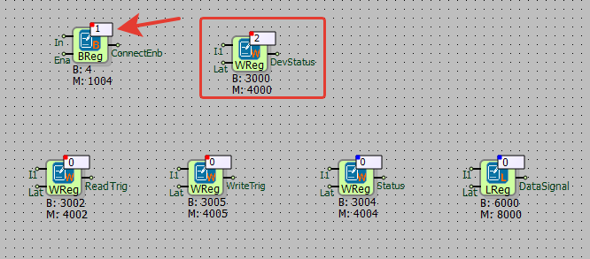
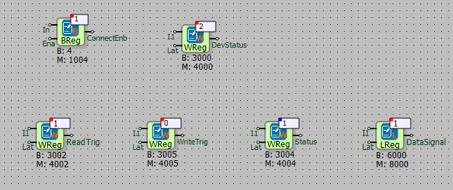
ConnectEnb Signal → Binary Register
DevStatus Signal → Word Register
Read Trig Signal, Write Trig Signal, Status Signal → Word Register
Data Signal → Long Register (A block is added from Telediagram to the Data Signal section based on the variable type specified in the MMS Type column.)

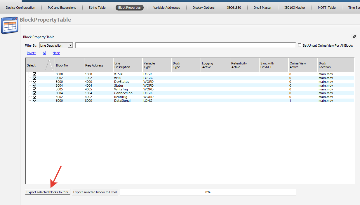
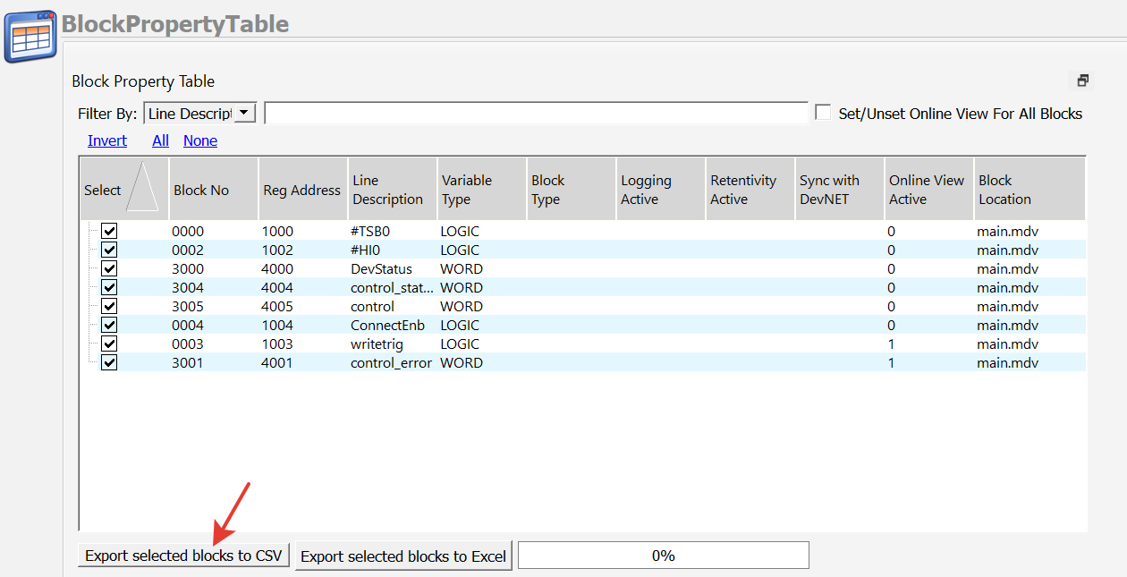
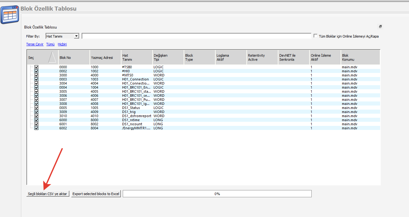
The blocks defined in Telediagram are exported in CSV format from the block properties table.
This process generates the data file required for integration with MDV61850 Browser.
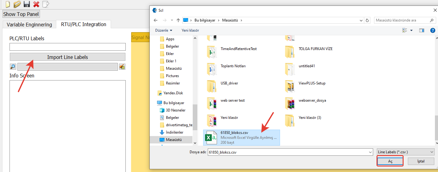
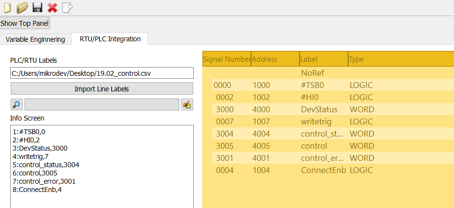
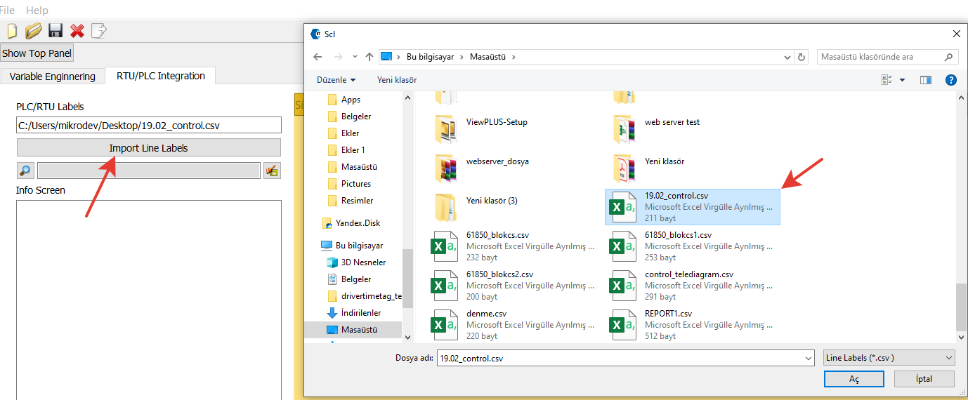
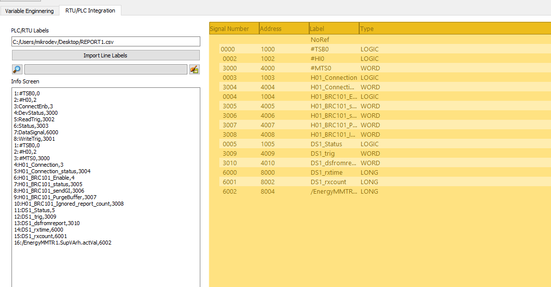
MDV61850 Browser is opened, and the RTU/PLC Integration section is accessed.
The CSV file obtained from Telediagram is imported.
Once the import is completed, the information screen displays the properties of the blocks.
On the right side of the screen, detailed information about the blocks is listed.

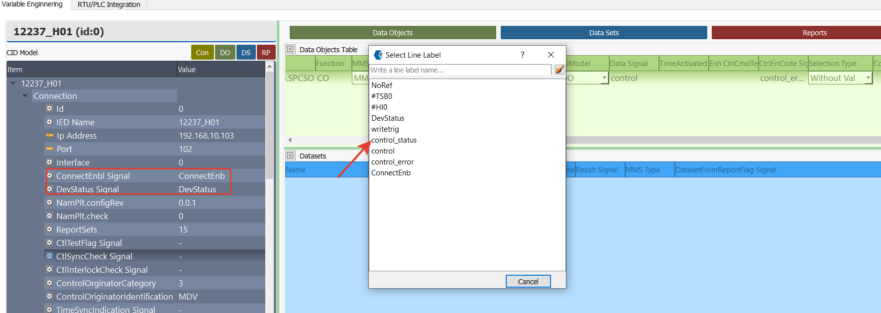
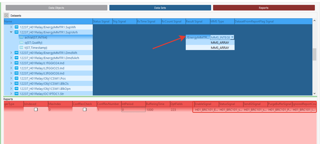
In MDV61850 Browser, the tag mapping process is performed using the following steps:
- Double-click on the relevant section where the tag should be mapped.
- In the Tag List window that appears, the available tags for mapping are displayed.
- Select the appropriate tag and map it to the corresponding section.

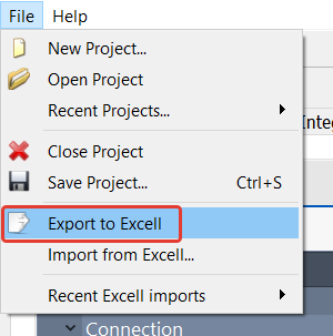
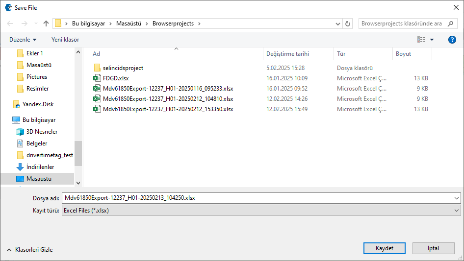
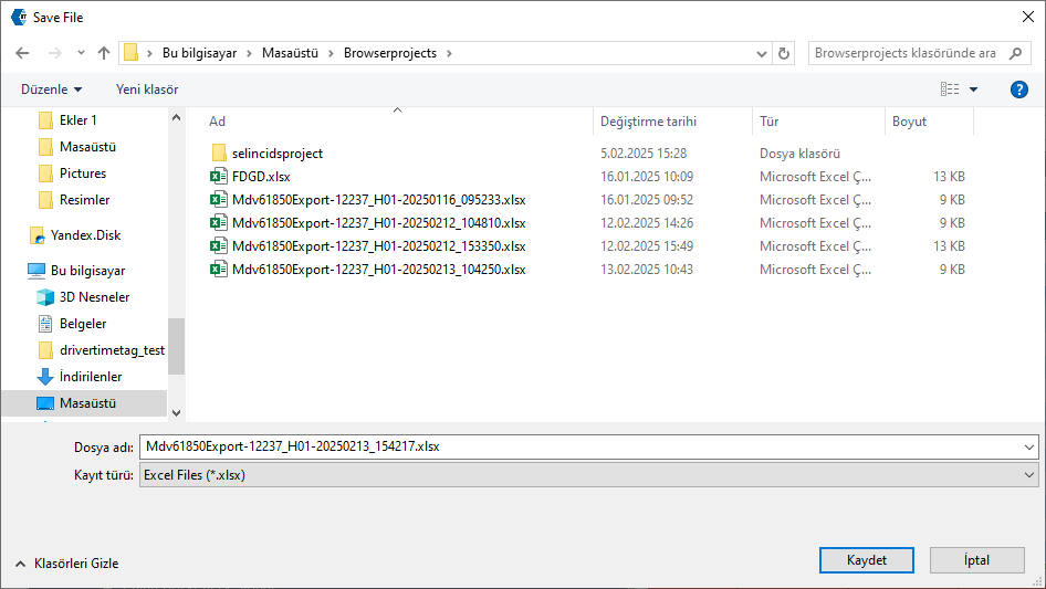
After completing the mapping process in MDV61850 Browser, the configuration can be exported in Excel format. From the File menu or file shortcuts, select the "Export to Excel" option.
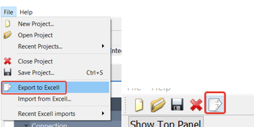
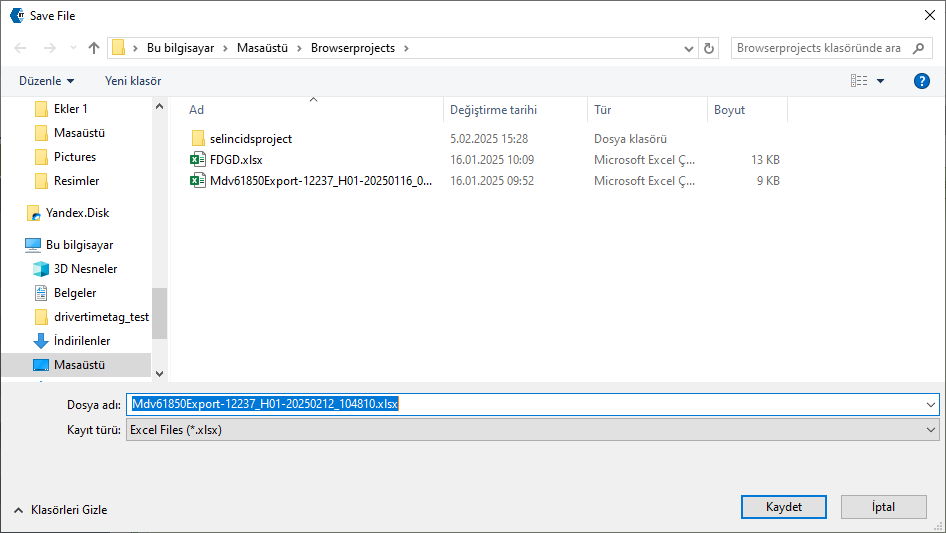
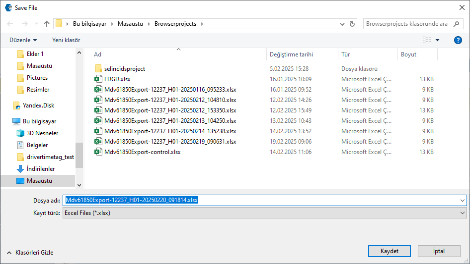
In the window that appears, select the file path where the Excel file will be saved and click the Save button.
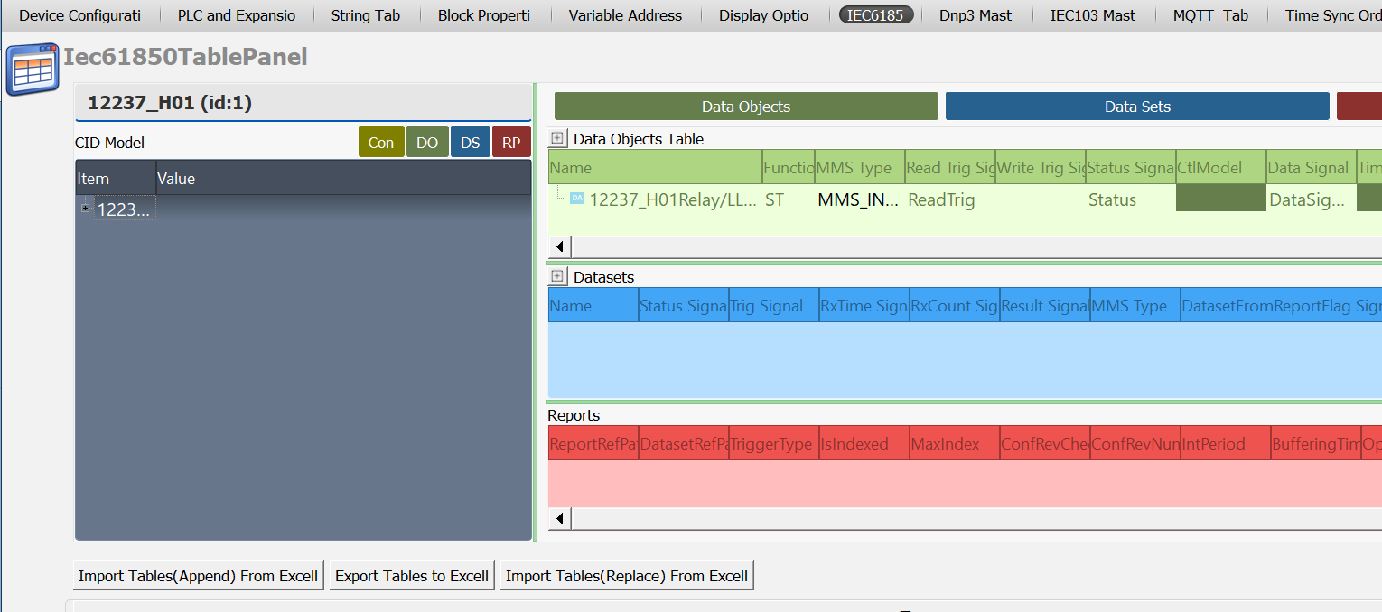
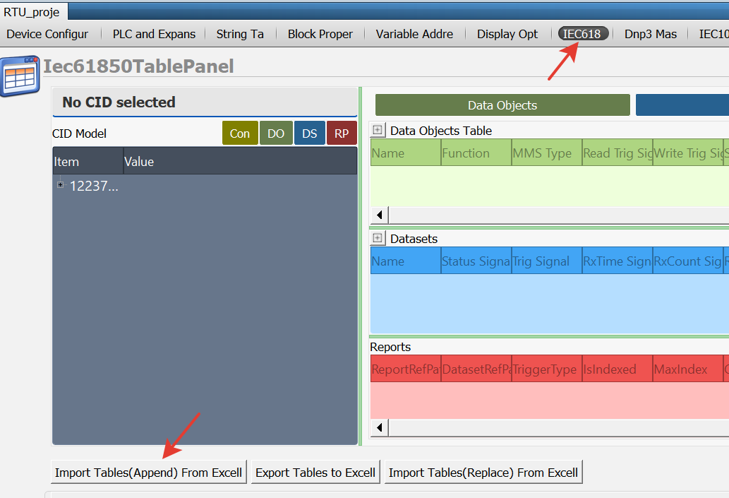
In Telediagram, the IEC 61850 table is opened, and the Excel file obtained from MDV61850 Browser is imported using the "Import tables (append) from Excel" option located at the bottom of the table.

Note: If a previously prepared IEC 61850 project exists and changes have been made in MDV61850 Browser, use the "Import Tables (Replace) from Excel" option to update only the relevant changes in the table.
When the Excel file is imported, the IEC 61850 Table automatically populates with the blocks selected from the Browser.
Once these steps are completed, the configuration required for communication between the relay and the RTU is finalized.
Finally, the RTU project created in Telediagram is uploaded to the device, making the system ready for operation.
After completing the configuration in MDV61850 Browser and Telediagram, follow these steps to test whether communication between the RTU and the relay is successful:
- Connect to the RTU device via Telediagram and enable online monitoring.
- To initiate communication between the RTU and the relay, send the value "1" to the ConnectEnb block. Monitor the Dev Status block to check the communication status between the RTU and the relay. If the Dev Status block displays the value "2", communication has been successfully established.
To read the data object value, a trigger is sent to the Read Trig block. The data object value is retrieved from the Data Signal block. The Status block is monitored to check whether the data object value has been successfully received.
Sending a Command to the Data Object
Open MDV61850 Browser from the Telediagram tools menu and select a previously prepared project file or create a new project.
In MDV61850 Browser, the data objects to which commands will be sent can be selected by double-clicking on them from the Data Objects List on the right side.
The selected objects will be displayed in the Data Objects Table on the right.
Note: Commands can only be sent to data objects with function code CO.
To send a command to a data object. Open MDV61850 Browser from the Telediagram tools menu and either create a new project or select a previously prepared project file. In MDV61850 Browser, double-click on the data object with function code CO in the Data Objects List on the right. This action will add the selected object to the Data Objects Table.

In the Connection section of MDV61850 Browser, the following blocks must be assigned through Telediagram to open/close the connection between the relay and RTU and to monitor the connection status:
ConnectEnb Signal: To open and close the connection with the relay. (detailed in Data Object Read)
DevStatus Signal: To monitor the connection status. (detailed in Data Object Read)
Write Trig Signal: Trigger input to send a command to the data object.
Status Signal: To track the status of the command sent to the data object. (detailed in Data Object Read)
CltModel: Parameter determining the control mode, and one of the following control modes can be selected:
DO (Direct-Operate): Provides direct control with normal safety precautions.
SBO (Select-Before-Operate): Provides control with select & operate logic with normal safety precautions.
DOes (Direct-Operate with Enhanced Security): Provides direct control with enhanced security precautions.
SBOes (Select-Before-Operate with Enhanced Security): Provides control with select & operate logic with enhanced security precautions.
Data Signal: : The value of the relevant data object on the relay is read via this block. The block to be associated from Telediagram is selected.
Time Activated Ctrl: Enables control commands to be executed with a specific timing. For example, scheduled operations such as opening or closing a circuit breaker at a specific time are performed.
Enh CtrlCmdTerm Signal: Used to ensure the termination of enhanced control commands. When the command operation is completed, this signal is activated. If the control command fails, error codes can be tracked via the CtrlErrCode Signal.
CtrlErrCode Signal: Explains the error reasons returned in case of failure of control commands. The block to be associated from Telediagram is selected. The possible values and their descriptions for this signal are as follows:
0 ADD_CAUSE_UNKNOWN Unknown error.
1 ADD_CAUSE_NOT_SUPPORTED Unsupported operation.
2 ADD_CAUSE_BLOCKED_BY_SWITCHING_HIERARCHY Blocked by switching hierarchy.
3 ADD_CAUSE_SELECT_FAILED Selection failed.
4 ADD_CAUSE_INVALID_POSITION Invalid position.
5 ADD_CAUSE_POSITION_REACHED Position already reached.
6 ADD_CAUSE_PARAMETER_CHANGE_IN_EXECUTION Parameter change occurred during execution.
7 ADD_CAUSE_STEP_LIMIT Step limit reached.
8 ADD_CAUSE_BLOCKED_BY_MODE Blocked by mode.
9 ADD_CAUSE_BLOCKED_BY_PROCESS Blocked by process.
10 ADD_CAUSE_BLOCKED_BY_INTERLOCKING Blocked by interlocking mechanism.
11 ADD_CAUSE_BLOCKED_BY_SYNCHROCHECK Blocked by synchronization check.
12 ADD_CAUSE_COMMAND_ALREADY_IN_EXECUTION Command is already being executed.
13 ADD_CAUSE_BLOCKED_BY_HEALTH Blocked due to health status.
14 ADD_CAUSE_1_OF_N_CONTROL Blocked due to 1/N control mechanism.
15 ADD_CAUSE_ABORTION_BY_CANCEL Operation canceled.
16 ADD_CAUSE_TIME_LIMIT_OVER Time limit exceeded.
17 ADD_CAUSE_ABORTION_BY_TRIP Operation canceled due to trip.
18 ADD_CAUSE_OBJECT_NOT_SELECTED Object not selected.
19 ADD_CAUSE_OBJECT_ALREADY_SELECTED Object is already selected.
20 ADD_CAUSE_NO_ACCESS_AUTHORITY Unauthorized access.
21 ADD_CAUSE_ENDED_WITH_OVERSHOOT Operation completed due to overshoot.
22 ADD_CAUSE_ABORTION_DUE_TO_DEVIATION Operation canceled due to deviation.
23 ADD_CAUSE_ABORTION_BY_COMMUNICATION_LOSS Operation canceled due to communication loss.
24 ADD_CAUSE_ABORTION_BY_COMMAND Operation canceled by command.
25 ADD_CAUSE_NONE No error.
26 ADD_CAUSE_INCONSISTENT_PARAMETERS Operation failed due to inconsistent parameters.
27 ADD_CAUSE_LOCKED_BY_OTHER_CLIENT Locked by another client.
Special 61850 Error Codes
100 E_61850CONTROL_ERROR_MODELMISMATCH Model mismatch error.
101 E_61850CONTROL_ERROR_INITIALIZATION Initialization error.
102 E_61850CONTROL_ERROR_TIMEOUT Timeout error.
Selection Type: Specifies the selection method to be used in control operations. With Value: The selection operation is performed by assigning a value to the target object during the selection process.
Without Value: The selection operation is done by only specifying the object; value specification is done in the next step.
Defines how the Select-Before-Operate (SBO) mechanism will be implemented.Command Type Signal: A signal used to determine the type of IEC 61850 control commands. This signal allows the RTU or SCADA system to determine how to send a control command.
Data Object Command Sending Application Example
Open the Telediagram application and create a new project. The signals defined in MDV61850 Browser are mapped to the appropriate register types in Telediagram. In this example, the following variables are selected:
- ConnectEnb Signal, Write Trig Signal → Binary Register
- Status Signal, Data Signal → Word Register (A block is added from Telediagram to the
- Data Signal section based on the variable type specified in the MMS Type column.)
- CltModel → DO is selected.
- Selection Type → Without Value is selected.

The blocks defined in Telediagram are exported in CSV format from the block properties table.
MDV61850 Browser is opened, and the RTU/PLC Integration section is accessed. The CSV file obtained from Telediagram is imported.

Once the import process is completed, the information screen displays the properties of the blocks. On the right side of the screen, detailed information about the blocks is listed.
In MDV61850 Browser, the tag mapping process is performed using the following steps:
- Double-click on the relevant section where the tag should be mapped.
- In the Tag List window that appears, the available tags for mapping are displayed.
- Select the appropriate tag and map it to the corresponding section.
After completing the mapping process in MDV61850 Browser, the configuration can be exported in Excel format. From the File menu, select the "Export to Excel" option.
In the window that appears, select the file path where the Excel file will be saved and click the Save button.
In Telediagram, the IEC 61850 table is opened, and the Excel file obtained from MDV61850 Browser is imported using the "Import tables (append) from Excel" option located at the bottom of the table.
When the Excel file is imported, the IEC 61850 Table automatically populates with the blocks selected from the Browser.

Once these steps are completed, the configuration required for communication between the relay and the RTU is finalized.
The RTU project created in Telediagram is uploaded to the device, making the system ready for operation. Connect to the RTU device via Telediagram and enable online monitoring.
To initiate communication between the RTU and the relay, send the value "1" to the ConnectEnb block. Monitor the Dev Status block to check the communication status between the RTU and the relay. If the Dev Status block displays the value "2", communication has been successfully established.
Enter a valueinto the block associated with Data Signal. Send a trigger from the Write Trig block. Monitor the Control Status and Control Error blocks to verify whether the command transmission was successful.

Data Set
Open MDV61850 Browser from the Telediagram tools menu and either create a new project or select a previously prepared project file.
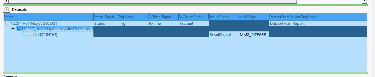
In MDV61850 Browser, the data sets to be read can be selected by double-clicking on them from the Data Sets List on the right. The selected data sets will be displayed in the Data Sets Table.
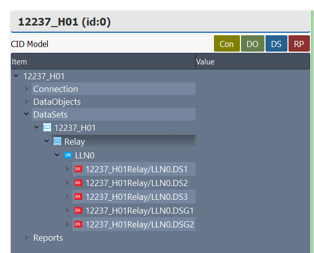
Note: The difference between data set reading and data object reading is that for data sets, it is not necessary to define separate status signal, trig signal, rx time signal, rx count signal, and data set from report flag signal for each data attribute.
In MDV61850 Browser, the following blocks must be assigned through Telediagram to open/close the connection between the relay and RTU and to monitor the status of data set processing:
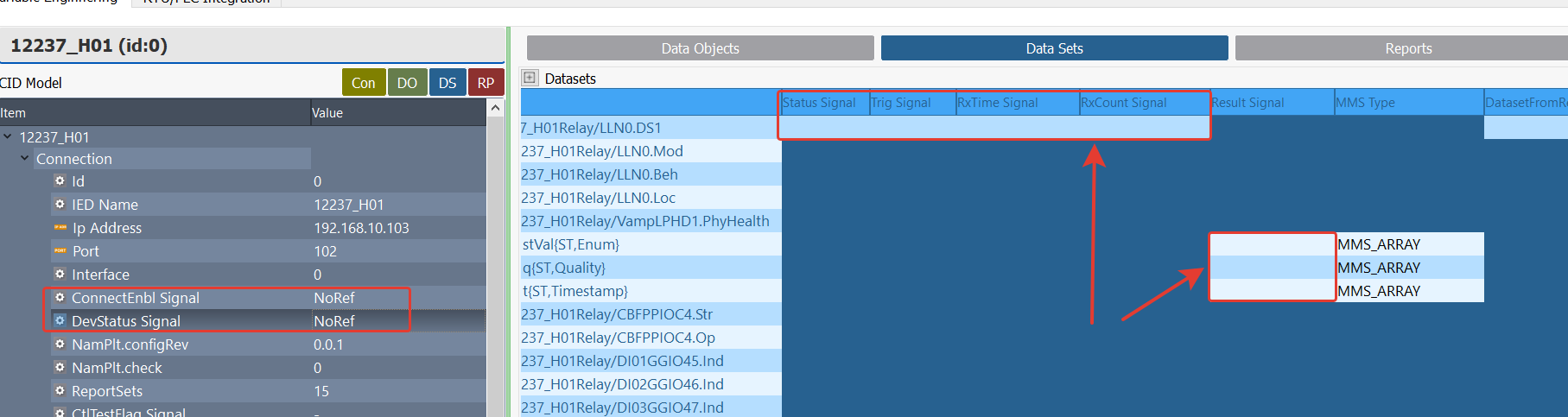
ConnectEnb Signal: To open and close the connection with the relay. (detailed in Data Object Read)
DevStatus Signal: To monitor the connection status. (detailed in Data Object Read)
Status Signal: Used to monitor the status of the reading operation. The block to be associated via Telediagram is selected. The possible values and their descriptions for this signal are as follows:
0: WAITING/FAIL, Waiting for request response or operation failed
1: OK, Request completed successfully.
2: MISMATCH, Operation failed due to incompatibility.
3: TIMEOUT, Operation failed due to timeout.
4: FAILED, Operation failed due to internal error.
100 and above: Operation failed due to library error. (Error code: status value - 100 can be calculated.)Trig Signal: The trigger block to be associated in Telediagram for reading data sets is selected.
RxTime Signal: Used to show the data reception time.
RxCount Signal: Used to track the number of data set receptions.
Result Signal: The value of the relevant data sets on the relay is read through this block. The block to be associated via Telediagram is selected.
MMS Type: Variable type. This section is automatically updated according to the data object selected in the project. (detailed in Data Object Read)
DatasetFromReportFlag Signal: Indicates whether the data set is received via the reporting mechanism.
Data Set Application Example
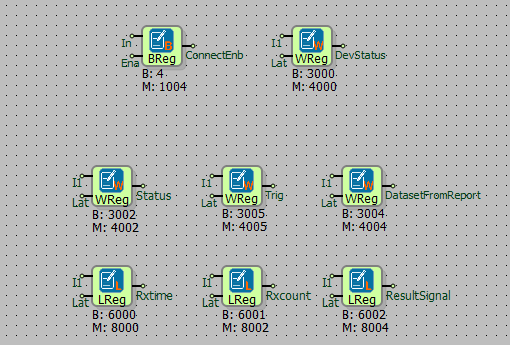
Open the Telediagram application and create a new project. The signals defined in MDV61850 Browser are mapped to the appropriate register type in Telediagram.
In this example, the following variables are selected:
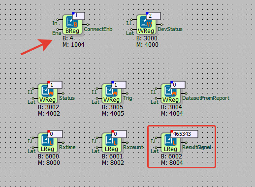
- ConnectEnb Signal → Binary Register
- DevStatus Signal → Word Register
- Status Signal, Trig Signal, Data Set From Report → Word Register
- RxTime Signal, RxCount Signal → Long Register
- Result Signal → Long Register (A block is added from Telediagram to the Result Signal section based on the variable type specified in the MMS Type column.)
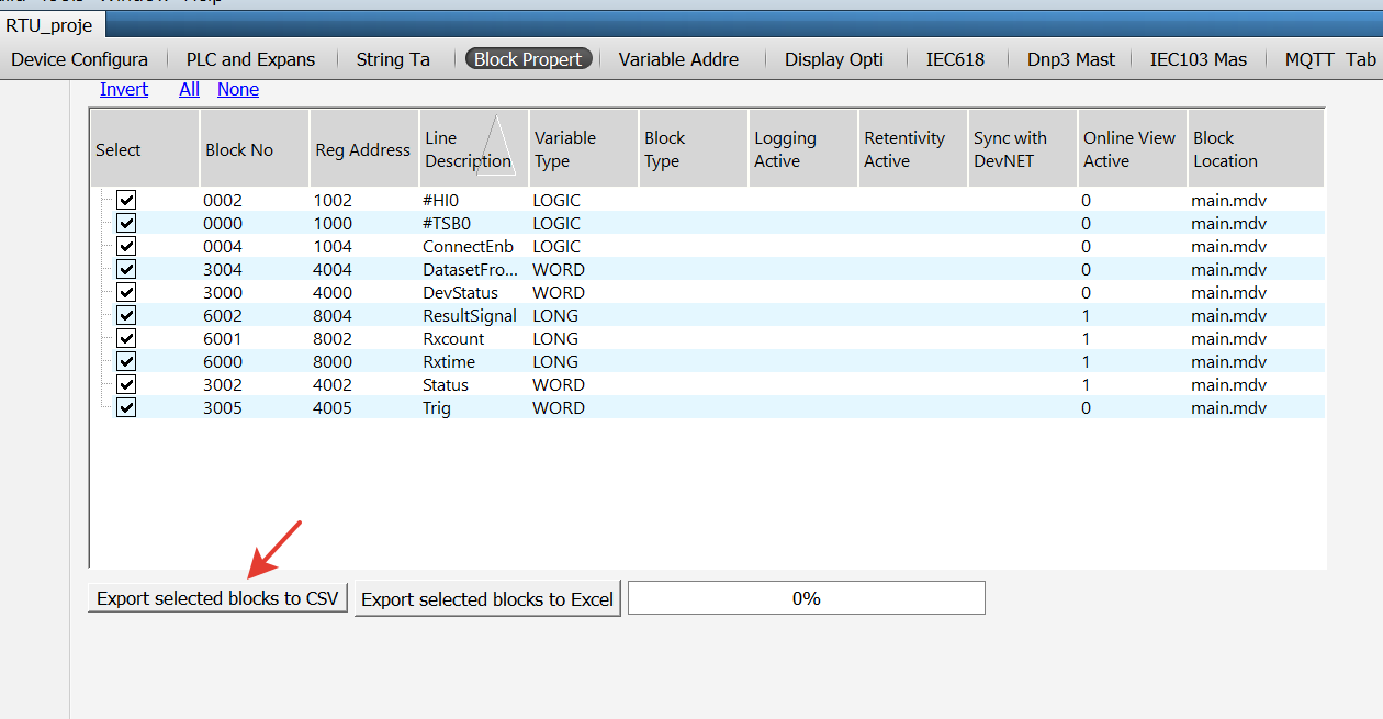
The blocks defined in Telediagram are exported in CSV format from the block properties table.
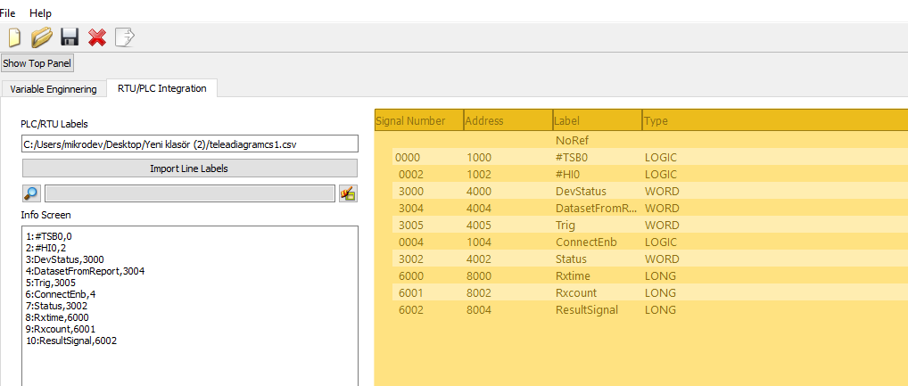
MDV61850 Browser is opened, and the RTU/PLC Integration section is accessed. The CSV file obtained from Telediagram is imported.
When the import process is completed, the information screen displays the properties of the blocks. On the right side of the screen, detailed information about the blocks is listed.
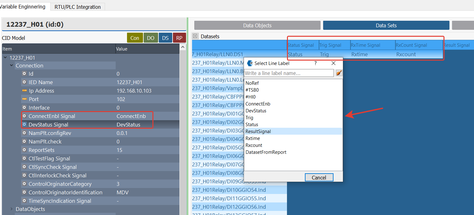
In MDV61850 Browser, the tag mapping process is performed using the following steps:
- Double-click on the relevant section where the tag should be mapped.
- In the Tag List window that appears, the available tags for mapping are displayed.
- Select the appropriate tag and map it to the corresponding section.
After completing the mapping process in MDV61850 Browser, the configuration can be exported in Excel format. From the File menu, select the "Export to Excel" option.
In the window that appears, select the file path where the Excel file will be saved and click the Save button.
The IEC 61850 table is opened in Telediagram, and the Excel file obtained from MDV61850 Browser is imported using the import tables (append) from excel option at the bottom of the table.

When the Excel file is imported, the IEC 61850 Table automatically populates with the blocks selected from the Browser.
When these steps are completed, the necessary configuration for communication between the relay and RTU is finalized. Finally, the RTU project created in Telediagram is uploaded to the device, making the system ready for operation.
After completing the configuration with MDV61850 Browser and Telediagram, the following steps are applied to test whether communication between the RTU and the relay is successful:
- Connect to the RTU device via Telediagram and enable online monitoring. To initiate communication between the RTU and the relay, send the value 1 to the ConnectEnb block.
- Monitor the Dev Status block to check the communication status between the RTU and the relay. If the Dev Status block displays the value 2, communication has been successfully established.
- To read the data set value, send a trigger to the Trig block. The data set value is retrieved from the Result Signal block. The Status block is monitored to check whether the data set value has been successfully received.
Report Reading
In the IEC 61850 protocol, reports are used to read data sets without triggering them.
Note: To successfully read reports, both the data set and the corresponding reports must be selected in MDV61850 Browser.
MDV61850 Browser is opened from the Telediagram tools menu, and either a new project is created or a previously prepared project file is selected.
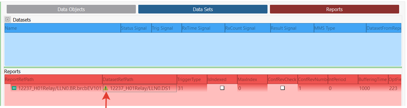
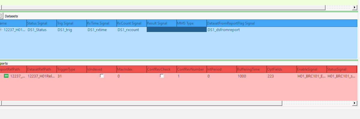
In the lower-left Reports section, the created reports are listed. The report to be read is added to the Reports table on the right by double-clicking it. It must be ensured that the DatasetRefPath of the added report in the Reports table matches the dataset name added to the Data Set Table.
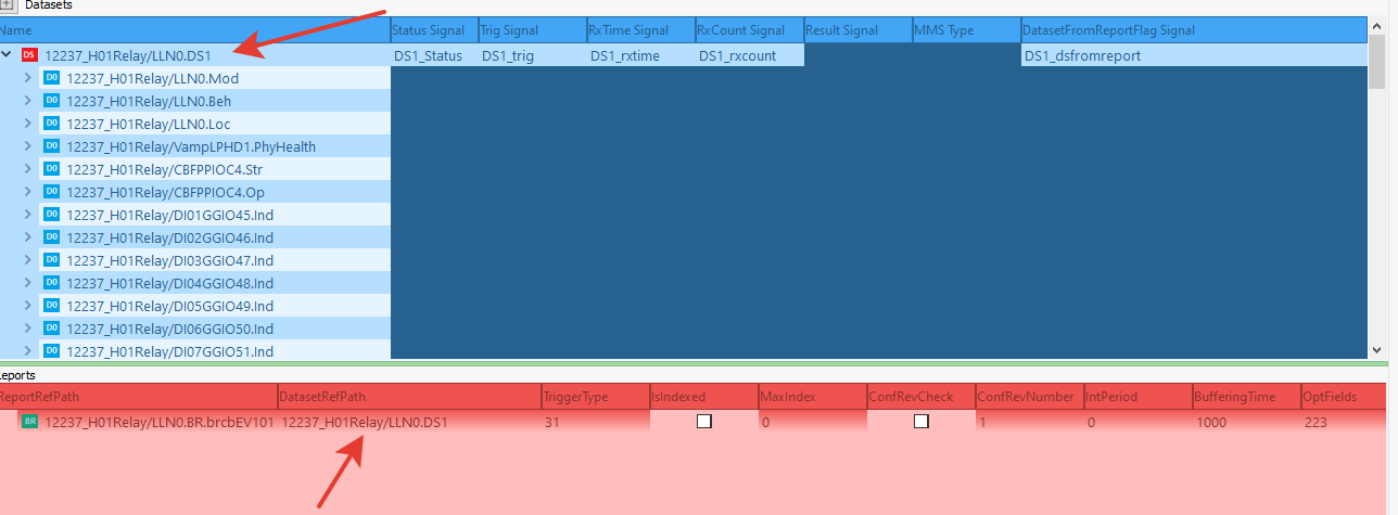
Report Ref Path: The file extension of the selected report.
Data Set Ref Path: The file extension of the data set to which the relevant report is linked.
Trigger Type: Determines under which trigger conditions the report will operate. When the Trigger Type column is double-clicked, the pop-up screen shown in Figure 45 opens.
- TRG_OPT_DATA_CHANGED: Send on data change.
- TRG_OPT_QUALITY_CHANGED: Send on quality change.
- TRG_OPT_DATA_UPDATE: Send when data is updated .
- TRG_OPT_INTEGRITY: Send periodically.
- TRG_OPT_GI: Send when a general interrogation request arrives.

Note: The following table shows how the Quality values in the IEC 61850 protocol are mapped to the RTU (Client) system within the MDV61850 Browser. In the RTU system, each quality status is expressed by a specific integer value.
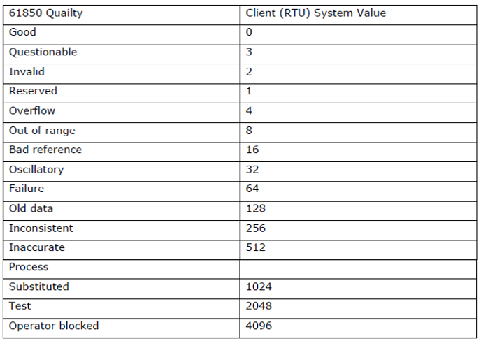
- IsIndexed: Determines whether the reports are indexed.
Indexed reports (Buffered Reports – BRCB) store past events and process them in a specific order.
Unindexed reports (Unbuffered Reports – URCB) transmit events only instantaneously.
If the IsIndexed value is 1, a Buffered Report is used.
MaxIndex: Determines the maximum index number for indexed reports. Determines the maximum number of events held when Buffered Reports (BRCB) are used. If the index value reaches the maximum, old records are deleted. For example, if there is a buffer memory for 1000 events, the oldest event is deleted, and the newly arrived event is recorded.
Conf Rev Check: Enables configuration revision control.
Conf Rev Number: Specifies the configuration revision number.
IntPeriod: Determines the reporting period of the report. If data will be sent periodically (if trigger type TRG_OPT_INTEGRITY is selected), the periodic sending time (in ms) should be entered in the Int Period column.
Buffering Time: This parameter determines how long buffered reports will store data. If BRCB is used, events are held in memory for a certain period. If Buffering Time is increased, it stores older events for a longer duration. If the buffer overflows, it can be manually cleared with the Purge Buffer Signal.
Opt Fields: Determines which additional fields the IEC 61850 reports will include. Report Time Stamp, ConfRev.
Enable Signal: The block to be associated via Telediagram to determine whether the report is enabled is selected.
Status Signal: The block to be associated via Telediagram to monitor the status of the report is selected. The possible values and their descriptions for this signal are as follows:
- INIT=0: Waiting for Enable Signal.
- REGISTER=1: Report activation is starting.
- WAITRCBVALUES=2: Report RCB read request sent, waiting for response.
- HASRCBVALUES=3: Report RCB read, activation process continues.
- WAITSETRCBVALUES=4: Report RCB updated, waiting for result.
- INSTALLED=5: Report installed, ready for report reception.
- ACTIVE=6: Report installed and at least one report received.
- FAILEDINIT=7: Report activation failed. The device will retry after 60 seconds.
- FORCETOCLOSE=8: Report deactivation request received, deactivation started.
- FORCETOCLOSE_WAITDISABLE=9: Deactivation process continues.
- FORCETOCLOSE_UNRESERVE=10: Reservation for deactivation is being removed.
- FORCETOCLOSE_WAITUNRESERVE=11: Deactivation process is completing.
Note: The ACTIVE (6) value indicates that the report is running successfully and at least one report has been received.
The FAILEDINIT (7) value indicates that the report activation process failed and the device will try again after 60 seconds.
The FORCETOCLOSE (8-11) values indicate that the report is in the deactivation process.
Send GI Signal: If GI is selected as the Trigger Type of the report, a trigger signal must be assigned to the Send GI Signal input. When a rising signal (1) is applied to this input, a General Interrogation (GI) request is triggered, and the report is sent.
Purge Buffer Signal: Used to clear the buffer memory in the report section in case of buffer overflow. If a buffer overflow occurs, the user can manually clear the buffer memory by applying a rising signal (1) to the input of the Telediagram block associated with the Purge Buffer Signal.
Ignored Report: Determines how the client handles report control block configuration revision mismatches. If the report control block configuration revision is incompatible, the report is not processed and is ignored. The number of reports ignored for this reason can be tracked via the IgnoredReportCount signal.
Note: When only a report is selected, an exclamation mark (!) appears in the Data Set Path section. For the report to work correctly, the relevant Data Set must also be added to the browser.
Data Set Not Selected;
Data Set Selected;
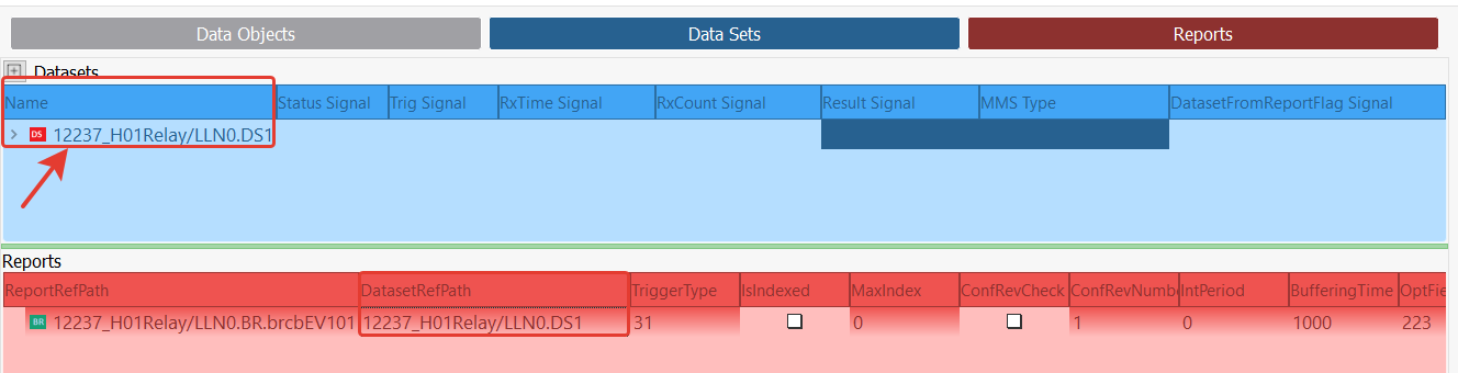
Note: Make sure that the DatasetRefPath value of the report added to the Reports table is the same as the dataset added to the Data Set Table.
Report Reading Application Example
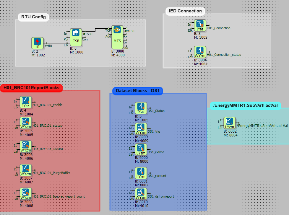
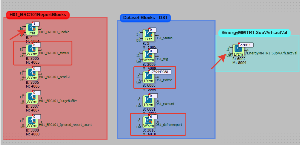
The signals defined in MDV61850 Browser are associated with appropriate register types in Telediagram. In the example described here, the following variables have been selected:
Blocks for connection with the relay:
- ConnectEnb Signal → Binary Register
- DevStatus Signal → Word Register
Blocks in the dataset table:
- Status Signal, Trig Signal, Data Set From Report → Word Register
- RxTime Signal, RxCount Signal → Long Register
- Result Signal → Long Register (A block is added from Telediagram to the data signal section according to the variable specified in the MMS Type field.)
Blocks in the report table:
- Enable Signal → Binary Register
- Status Signal, Send GI Signal, Purge Buffer Signal, Ignored Report Count → Word Register
The blocks defined in Telediagram are exported to CSV format from the block properties table.
The MDV61850 Browser is opened, and the RTU/PLC Integration section is accessed.
The CSV file obtained from Telediagram is imported.

Once the import is complete, the information screen displays the properties of the blocks. Detailed information about the blocks is listed on the right screen.
In MDV61850 Browser, the tags must be matched. The relevant section where the tag will be assigned is double-clicked. In the opened Tag List window, the tags to be matched with the relevant section are displayed.
The appropriate tag is selected and matched with the corresponding section.
After the matching process is completed in MDV61850 Browser, the configuration can be exported in Excel format. From the File menu, the Export to Excel option is selected.

In the opened window, the file path for saving the Excel file is selected, and the Save button is clicked.
In Telediagram, the IEC 61850 table is opened, and the Excel file obtained from MDV61850 Browser is imported using the "import tables (append) from Excel" option located at the bottom of the table.

Once the Excel file is imported, the IEC 61850 Table automatically displays the blocks selected from the Browser. This ensures that all required signals and configurations are correctly transferred to Telediagram without manual input.
When these steps are completed, the necessary configuration for communication between the relay and the RTU is finalized. This step is critical because it establishes the signal mapping required for successful data exchange.
Finally, the RTU project created in Telediagram is uploaded to the device, making the system ready for operation. Ensuring a successful upload is important to avoid configuration mismatches.
After completing the configuration using MDV61850 Browser and Telediagram, the following steps are applied to test whether communication between the RTU and the relay is successful:
- Connect to the RTU device via Telediagram and open online monitoring. This allows real-time observation of data exchange.
- To start communication between the RTU and the relay, set the ConnectEnb block to 1. This enables the communication link. Monitor the Dev Status block to check the communication status between the RTU and the delay. If the Dev Status block shows the value 2, communication has been successfully established. Any other value might indicate a configuration issue or connection failure.
- When the Report Enable tag is set to 1, the Report Status and Data Set From Report blocks should receive the value 6. This confirms that the report mechanism is functioning properly.
- In the RxTime Signal, the dataset value's read time should be displayed in epoch time. This ensures that timestamps are correctly processed. The Result Signal should display the current value of the dataset. Any discrepancies in the expected values might indicate issues in data mapping or communication delays.
By following these steps, the successful communication between the RTU and the relay can be verified, ensuring that the system is correctly configured and operational.