MDC100 Software Manual
MODC Gateway Configuration Software
General Information
The Assistant software is used to make all necessary settings for the Mikrodev Gateway devices. Thanks to the software, device settings can be made online and/or offline. The settings that are loaded on the device can easily be downloaded and the previously saved settings can easilly be uploaded into the device by the program. The connection between the program and the device can be established in various ways such as USB, Ethernet, GSM, Wi-Fi. For Ethernet supported devices; there is also the ability to search the network and list details with connection information.
Device Connection
USB Serial Connection
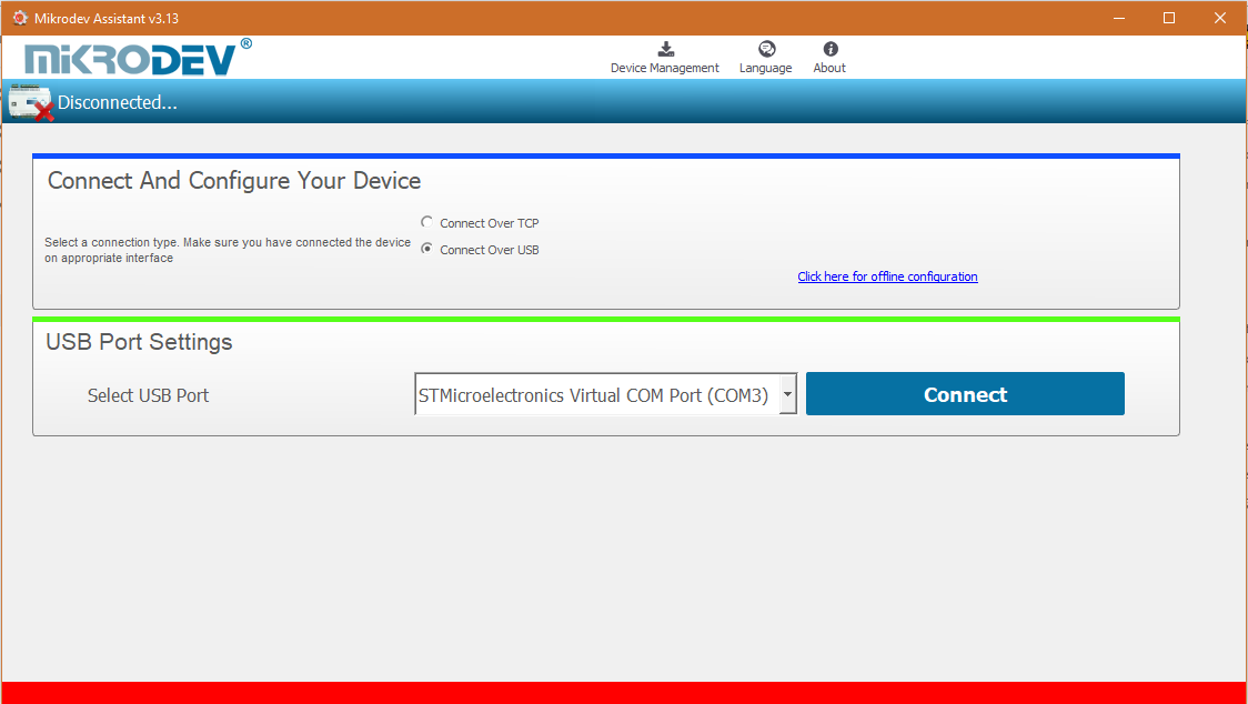
One of the methods for establishing communication between PC and Mikrodev device in device configuration is USB serial connection. In order to perform USB connection between PC and device, you need to install USB driver for PCs with Windows 7/8 / 8.1 operating systems. There is no need to install the USB driver for Windows 10 operating systems. For serial connection over USB, “Connect over USB" box in the Connect and Configure Your Device section of the Assistant software is selected. In the USB Port Selection section, you should select the port and click "Connect". USB connection will be established after that.
TCP Connection – Device Discovery Mode
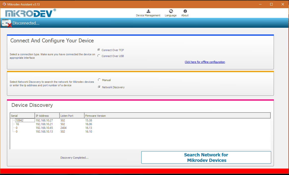
"Network Discovery" option is used to detect and connect IP addresses of Mikrodev devices which are active in the local network. The "Network Discovery " box will be highlighted after the "Connect via TCP" box is checked in the Connect and Configure to Device section of the Assistant software. After clicking "Scan Network for Mikrodev Devices", the serial number, IP address, listening port and software versions of all Mikrodev devices which are active in the network are listed on the screen. You can connect the device on the list by double clicking on the device name on the screen.
TCP Connection – Manual
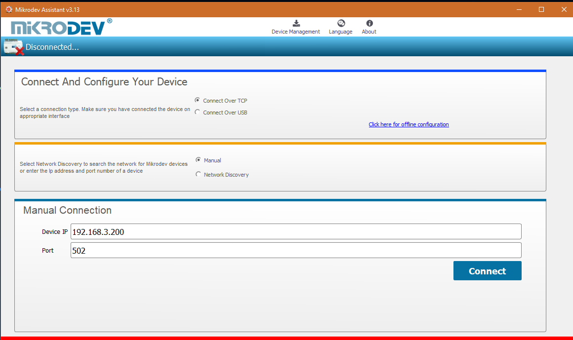
When manually entering the ip address and port number of the device that is active in the local network, "Manual" option is used. The "Manual" box is checked after the "Connect over TCP" checkbox is checked in the Connect and Configure Device section from the Assistant software. The IP address of the device to be connected is entered into the "Device IP" section, the port number is entered into the "Port" section and "Connect" is clicked. Assistant software connects to the Mikrodev device with specified ip address and port number.
Offline Settings
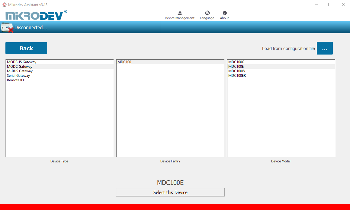
Offline mode is used when parameter settings are made and saved without connecting to the device. Click on "Click here for offline configuration" on the Assistant main screen when you want to make the offline parameter settings. The device is selected in the screen that appears, and then "Select this device" is clicked. Offline parameter settings of the selected device can be made. In addition, using the "Load from configuration file" option on the same page, previously saved configuration values can also be loaded to the program.
MODC Gateway Settings
Status Screen
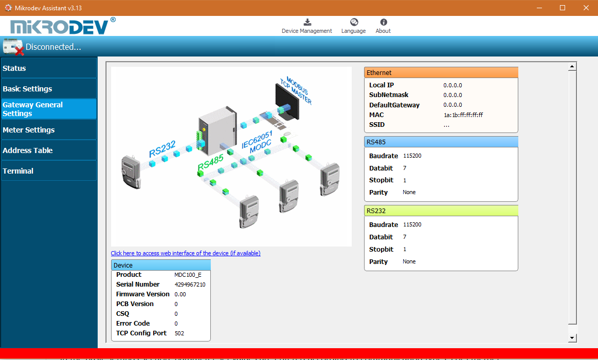
It is the status information screen which shows related information to the connected Mikrodev device. This screen contains the device's manufacturing information, Ip settings and serial connection settings (RS-485, RS-232). You can access the web interface of the device from this screen as well. Select "Click here to access the web interface of the device" to access the web interface.
Basic Settings
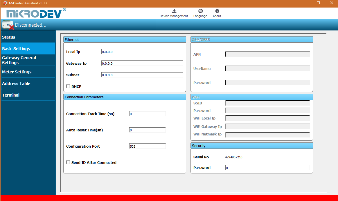
In the basic settings section, parameter set values are entered according to communication types. For Ethernet connection enter the local ip, gateway ip, subnet and for GSM connection enter the APN, user name, user password. SSID (Modem user name) and password are entered when wifi connection is requested. In addition; the password definition for access control to the Mikrodev device is performed on this page. In addition, device connection follow-up duration, auto reset duration, and configuration port can be entered. You can send ID after connection by checking the "Send ID after connection" checkbox.
MODC General Settings
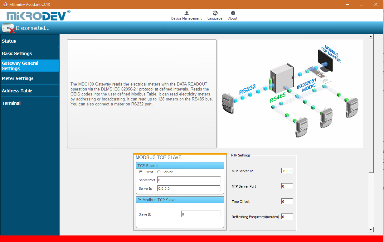
In the ModC General Settings section, the Modbus communication settings of the Mikrodev device are made. In case of connection via Modbus TCP, server or client selection of the connection type is made and port settings are defined. And also, Modbus Slave ID settings are defined.
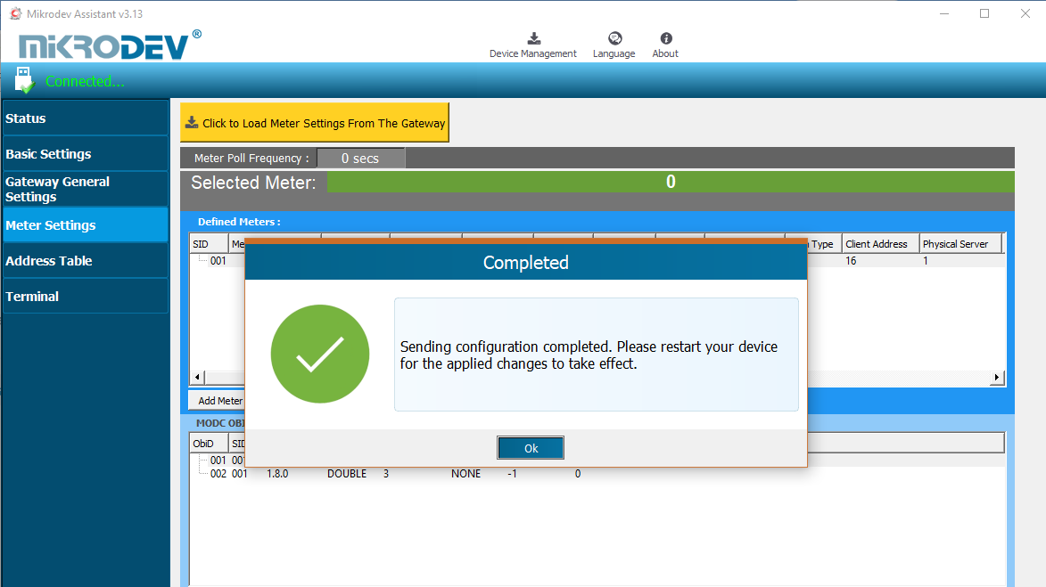
Loading Settings to Device
Click "Device Management" on the Assistant software to send the configuration settings to the device. Then click "Send Configuration" option.
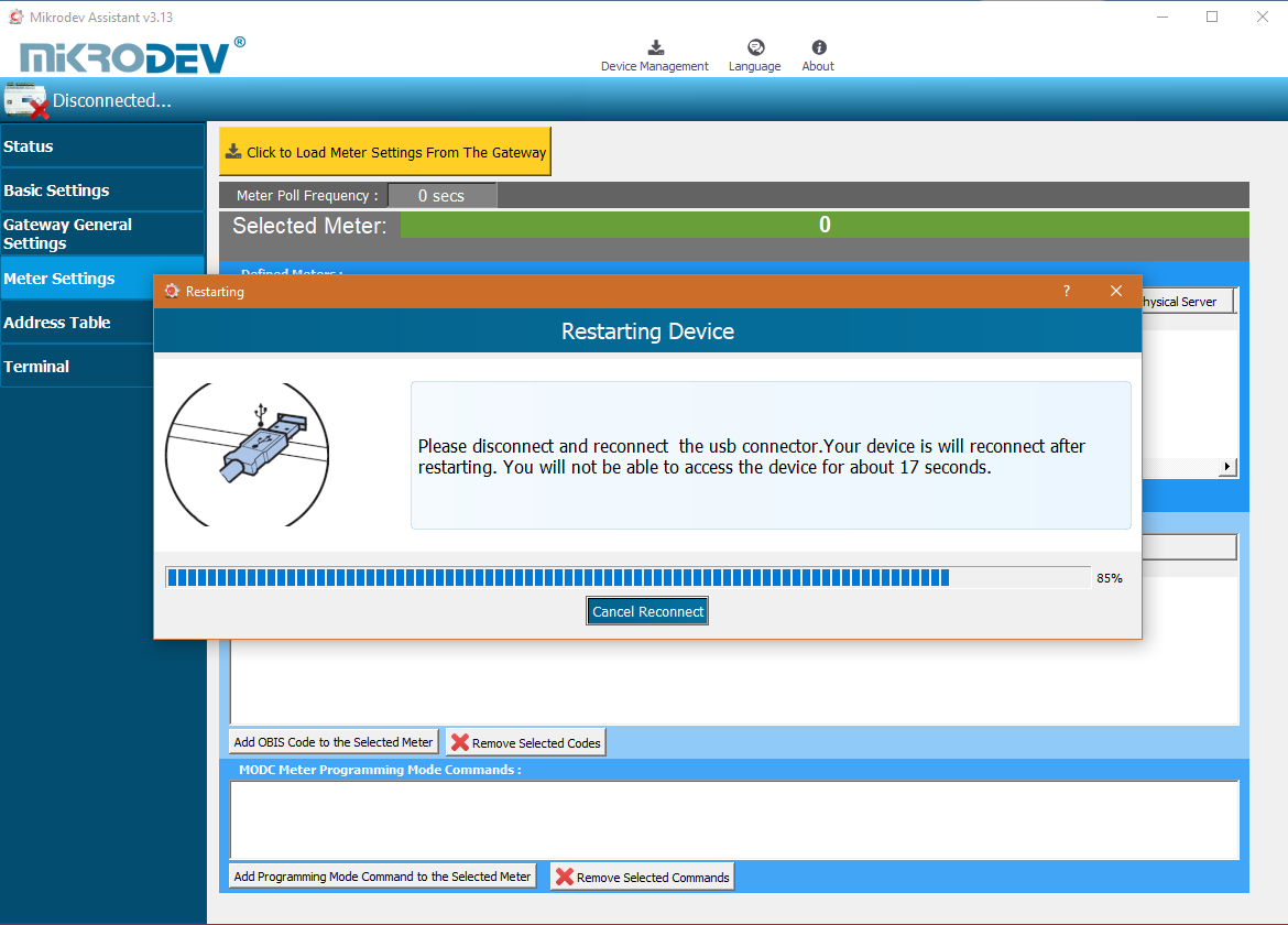
After completing the configuration, the device must be rebooted in order to register the settings.
Restart the device by clicking "Restart Device" under "Device Management" on the main screen of the Assistant program. When the device is rebooted, you may need to remove and reinsert the USB cable to reconnect with the serial port.
The TCP connection between the device and the PC will be established automatically after the device is rebooted, after waiting approximately 20 seconds to reconnect to the device through the TCP connection.
MODC Gateway Parameter Settings
Adding Meters
MODC Gateway support addressing mode or non-adressing boardcasting mode. If you want to read meter without addressing, you should give 0 into Meter Serial No. if not you should give serial number for addressing.
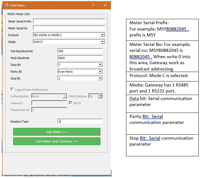
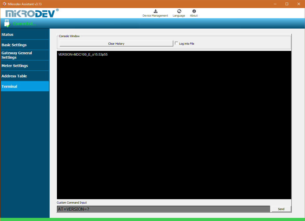
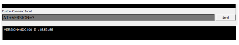
Port terminal places might difference according to pcb version of device. To do right configuration connect over USB to device and check version with AT commands. Response from device should be like below.
• If pcb version is p55 ; o Port 1 -> RS 232 (ROUTE 1) o Port 2 -> RS 485 (ROUTE 2)
• If pcb version is p66 ; o Port 1 -> RS 485 (ROUTE 1) o Port 2 -> RS 232 (ROUTE 2)
Adding OBIS Codes
To define the OBIS codes to be read out from the electricity meters, first click on the meter from the list of defined meters. Then click "Add OBIS Code to Selected Meter " on the Modc Settings page. The OBIS value to be read is entered in the "OBIS Name" section in the opened page. (Eg 0.0.0, 1.8.0, ...) In the "Code 1 Type" section, the variable type of the value from the relevant OBIS code is selected. If more than one value is read from an OBIS code to be defined, the variable type of the second value to be read is selected in the "Code 2 Type" section.
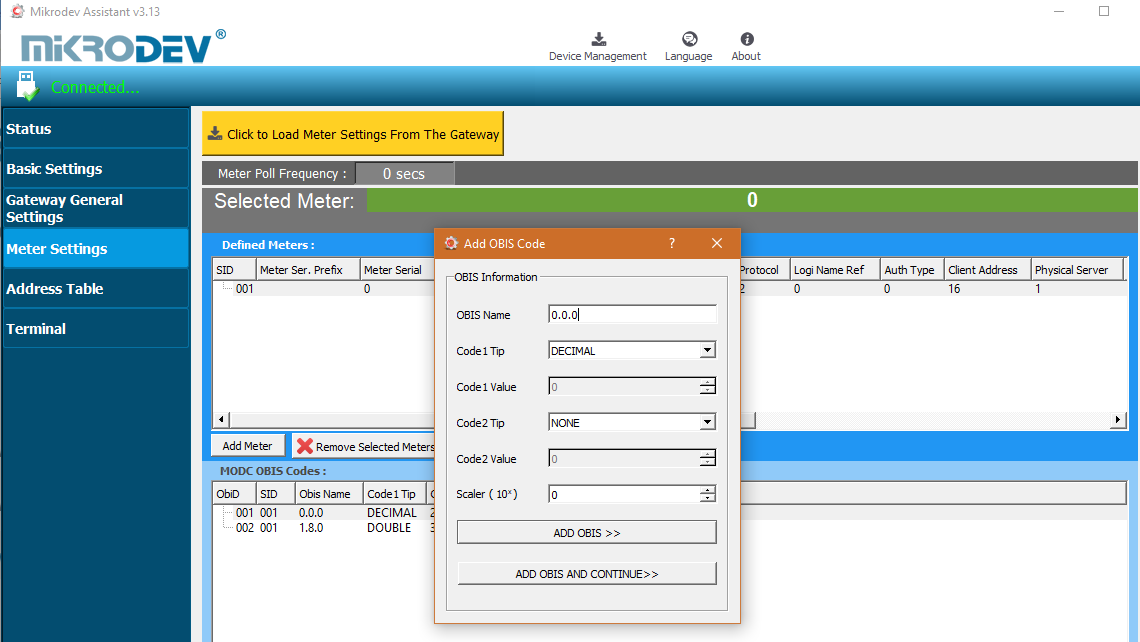
After all settings are made, click "Add OBIS". If more than one OBIS code is to be defined, the "Add and Continue OBIS" option is clicked. Here you can add new OBIS codes in succession. If you want to modify the OBIS codes created in the MODC OBIS Codes list, you can click on the parameter to be modified and make changes.
Adding OBIS Codes with Special Commands
Special instructions may be required to read certain information on the electricity meters. In such cases, the specific command information must be requested from the electricity meter's manufacturer. In order to add OBIS code with special command, click "Add Programming Mode Command to Selected Meter" option on the ModC Settings page. In the incoming screen, special command input is entered in the "Command" section.
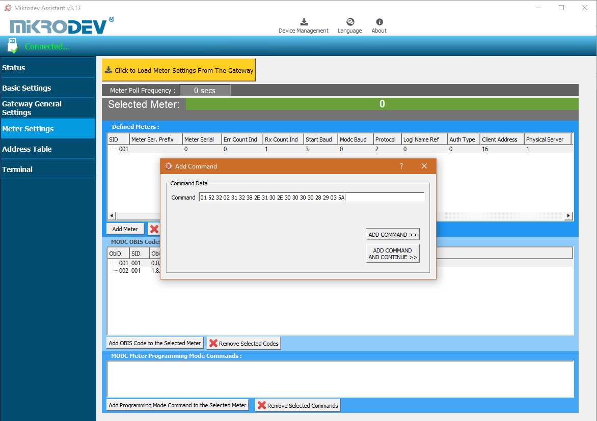
After all settings are made, click "Add Command". If more than one custom command will be added, the "Add Command and Continue" option is clicked. You can add successive OBIS codes in this way. MODC If you want to change the special commands created in the MEter Programming Mode Commands list, you can click on the parameter to be changed and make changes.
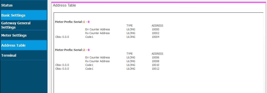
MODBUS Adress Table
MODBUS address table shows the type of OBIS codes defined earlier and corresponding modbus addresses.
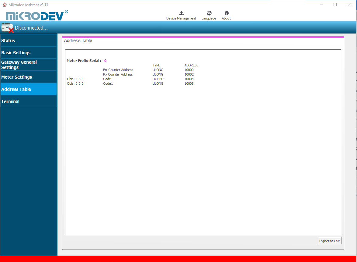
Addresses in the Modbus Address Table start at 10,000. The first two addresses of each counter added to the table represent error counter and rx counter values. When adding new OBIS code definitions it should be noted that; when multiple meters are defined on the system, if a new OBIS code value is defined on the first meter, the modbus addresses of the latter meters also change. For this reason, it is necessary to go through the next meter after defining all the parameters of the previous meters completely.
Terminal
Terminal window is the section where the commands for the MMS100 series converters are entered. In this section, information coming from the device is displayed on the screen. In the "Custom Command Input" section, type the command to be queried (eg AT + VERSION =?) And click "Send" to send the query to the device. The query answer appears on the screen. Click on "Clear History" in the "Console Window" section to clear the queries that are displayed on the screen.