MMS100 Software Manual
M-BUS Gateway Configuration Software
General Information
The Assistant software is used to make all necessary settings for the Mikrodev Gateway devices. Thanks to the software, device settings can be made online and/or offline. The settings that are loaded on the device can easily be downloaded and the previously saved settings can easilly be uploaded into the device by the program. The connection between the program and the device can be established in various ways such as USB, Ethernet, GSM, Wi-Fi. For Ethernet supported devices; there is also the ability to search the network and list details with connection information.
Device Connection
USB Serial Connection
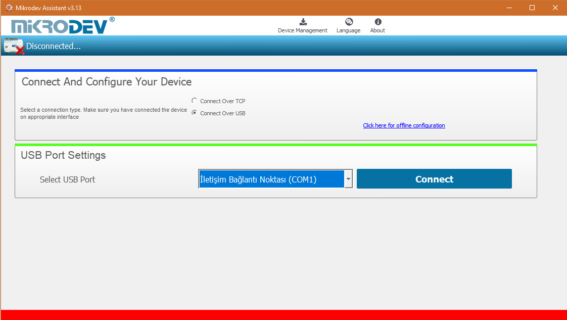
One of the methods for establishing communication between PC and Mikrodev device in device configuration is USB serial connection. In order to perform USB connection between PC and device, you need to install USB driver for PCs with Windows 7/8 / 8.1 operating systems. There is no need to install the USB driver for Windows 10 operating systems. For serial connection over USB, “Connect over USB" box in the Connect and Configure Your Device section of the Assistant software is selected. In the USB Port Selection section, you should select the port and click "Connect". USB connection will be established after that.
TCP Connection – Device Discovery Mode
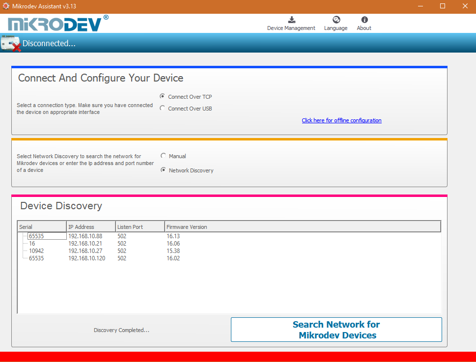
"Network Discovery" option is used to detect and connect IP addresses of Mikrodev devices which are active in the local network. The "Network Discovery " box will be highlighted after the "Connect via TCP" box is checked in the Connect and Configure to Device section of the Assistant software. After clicking "Scan Network for Mikrodev Devices", the serial number, IP address, listening port and software versions of all Mikrodev devices which are active in the network are listed on the screen. You can connect the device on the list by double clicking on the device name on the screen.
TCP Connection – Manual
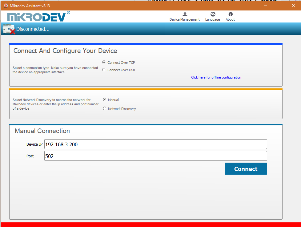
When manually entering the ip address and port number of the device that is active in the local network, "Manual" option is used. The "Manual" box is checked after the "Connect over TCP" checkbox is checked in the Connect and Configure Device section from the Assistant software. The IP address of the device to be connected is entered into the "Device IP" section, the port number is entered into the "Port" section and "Connect" is clicked. Assistant software connects to the Mikrodev device with specified ip address and port number.
Port Numbering
Port terminal places might difference according to pcb version of device. To do right configuration connect over USB to device and check version with AT commands.

Response from device should be like below.
![]()
Check the pcb version number placed to last 3 character of response like “pXX”
VERSION=MBS100_E_s15.52p66
• If pcb version is p55 ;
o Port 1 -> RS 232 (ROUTE 1) o Port 2 -> RS 485 (ROUTE 2)
• If pcb version is p66 ;
o Port 1 -> RS 485 (ROUTE 1) o Port 2 -> RS 232 (ROUTE 2)
Offline Settings
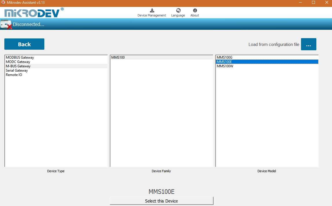
Offline mode is used when parameter settings are made and saved without connecting to the device. Click on "Click here for offline configuration" on the Assistant main screen when you want to make the offline parameter settings. The device is selected in the screen that appears, and then "Select this device" is clicked. Offline parameter settings of the selected device can be made. In addition, using the "Load from configuration file" option on the same page, previously saved configuration values can also be loaded to the program.
M-BUS Gateway Settings
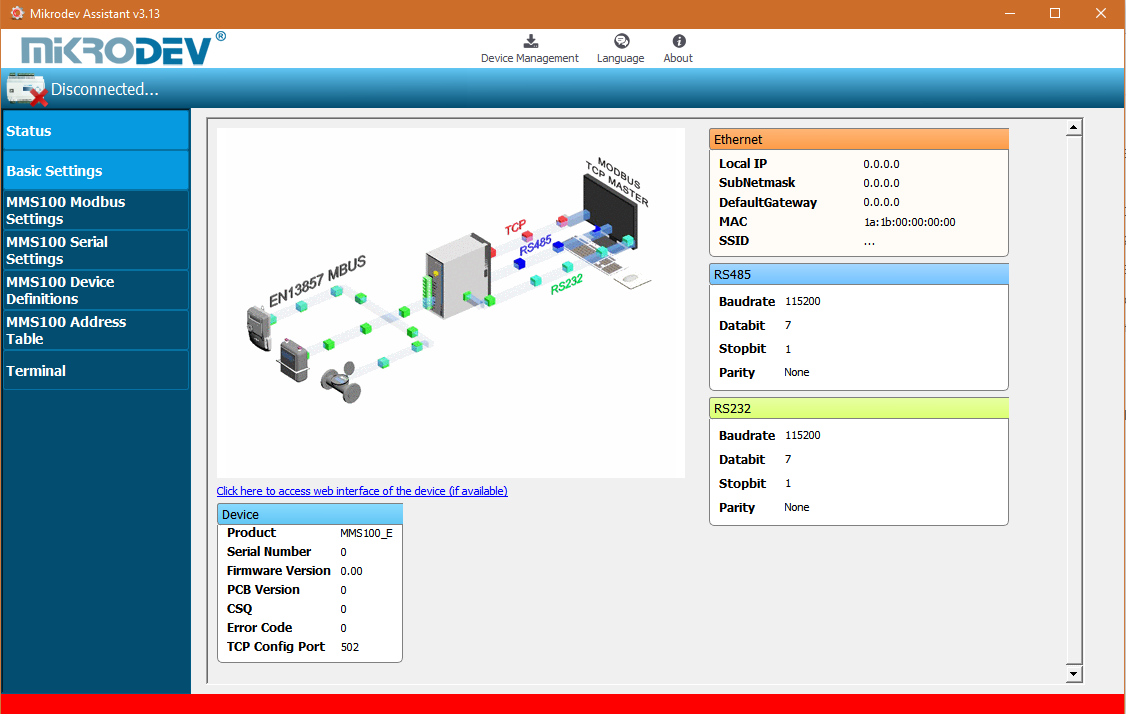
Status Screen
It is the status information screen which shows related information to the connected Mikrodev device. This screen contains the device's manufacturing information, Ip settings and serial connection settings (RS-485, RS-232). You can access the web interface of the device from this screen as well. Select "Click here to access the web interface of the device" to access the web interface.
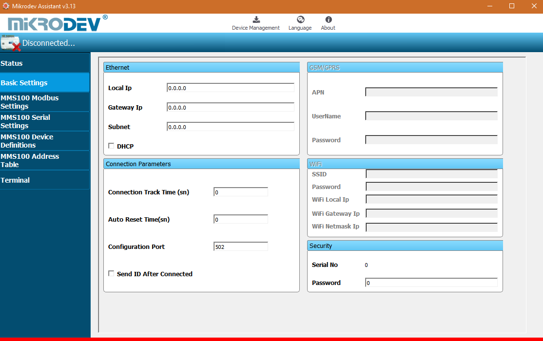
Basic Settings
In the basic settings section, parameter set values are entered according to communication types. For Ethernet connection enter the local ip, gateway ip, subnet and for GSM connection enter the APN, user name, user password. SSID (Modem user name) and password are entered when wifi connection is requested. In addition; the password definition for access control to the Mikrodev device is performed on this page. In addition, device connection follow-up duration, auto reset duration, and configuration port can be entered. You can send ID after connection by checking the "Send ID after connection" checkbox.
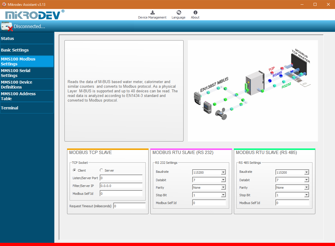
MMS100 Modbus Settings
In the Modbus settings section of the MMS100, the Modbus communication settings of the Mikrodev device are made. In the case of connection via Modbus TCP, connection type, server or client selection and port settings are made. Depending on the serial(RTU) connection type selection (RS-232, RS-485) of the MMS100 series Gateway, the corresponding box is checked and the Ip setting, port number, baud rate, databit value, parity value and stop bit are set.
Loading Settings to Device
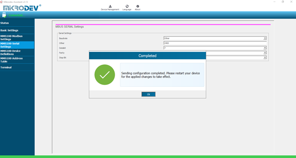
Click "Device Management" on the Assistant software to send the configuration settings to the device. Then click "Send Configuration" option.
After completing the configuration, the device must be rebooted in order to register the settings.
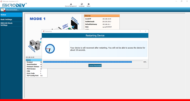
Restart the device by clicking "Restart Device" under "Device Management" on the main screen of the Assistant program. When the device is rebooted, you may need to remove and reinsert the USB cable to reconnect with the serial port.
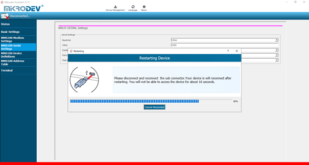
The TCP connection between the device and the PC will be established automatically after the device is rebooted, after waiting approximately 20 seconds to reconnect to the device through the TCP connection.
M-BUS Gateway Parameter Settings
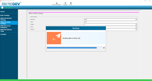
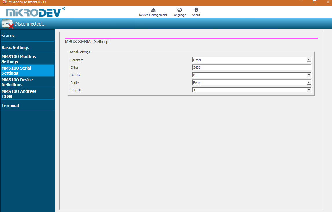
MMS100 Serial Communication Settings
The serial (RTU) connection settings of the MMS100 series gateways are defined in this section. The baud rate, databit value, parity value and stop bit value of the device or devices (water meters, natural gas meters, calorimeters ...).
MMS100 Device Definitions
The query sending period of the Mikrodev MMS100 series gateways are defined in the "Poll Frequency" section. The value is entered in seconds. The number of devices to be connected with the MMS100 series gateway is determined in the "Device Count" section. In the "Physical Device Address" section, the number of slots specified in the "Device Count" section starts from 1 and appended. In this section, the slave addresses of the devices in the field are defined. "Physical Device Address" is the section where the Modbus addresses are determined according to the device selections.
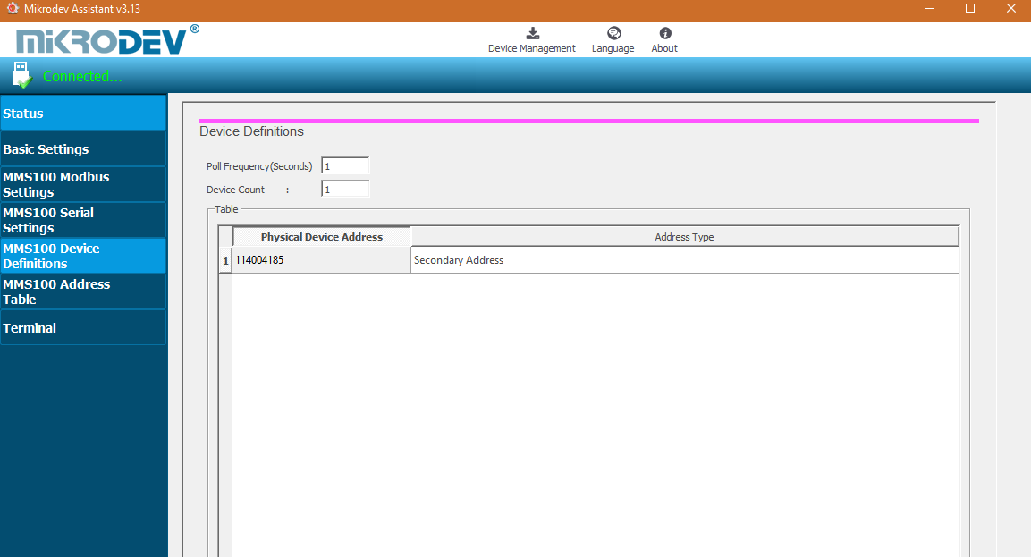
• If the watch serial number is entered, the 2nd address is selected, if not, the 1st address is selected. • The update period and the number of devices are selected above.
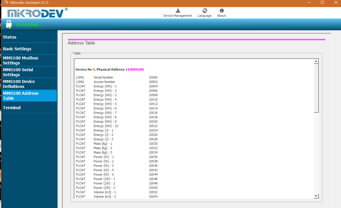
MMS100 Address Table
MMS100 Address Table section is the section in which the MBUS information of the MMS100 series gateways are written to which Modbus address. In this section, device numbers, physical addresses (slave addresses), data types, the names of the addresses and the addresses of the modbus are displayed.
Terminal
Terminal is the section where the command lines for the MMS100 series gateways are entered. In this section, information coming from the device is listed on the screen. In the "Custom Command Input" section, type the command to be queried (eg AT + VERSION =?) And click "Send" to send the query to the device. The query answer appears on the screen. Click "Clear History" in the "Console Window" section to clear the inquiries on the screen.
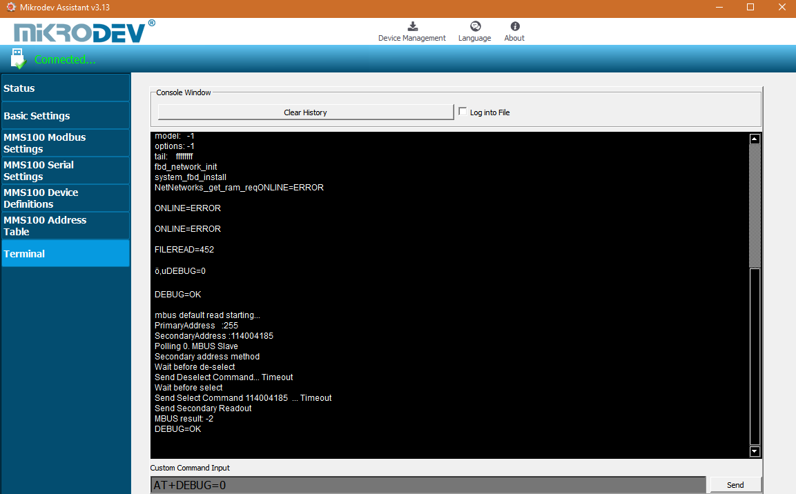
• AT+DEBUG= ?from the terminal. it is checked to see if there is a problem, if it turns 0, there is no problem with the device.
• AT+DEBUG=1 M-bus communication is checked from the terminal, if M-bus is -2, it does not communicate.